Friday, May 12, 2017

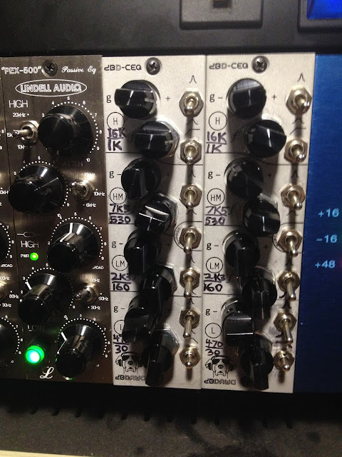
500 Series EQ DIY - Calrec PQ1549, kit named CEQ from DBDawg

A few years ago, I saw this kit for sale, and eventually bought a couple on sale.  They are no longer made, and the seller seems to be making motorcycle parts.  If you are on the market for something like a Calrec EQ, there is the RTZ Audio PEQ-1549 which comes highly recommended, and the Gyraf Audio DIY project is still out there, which is probably what this DBD kit is based on.

Flash forward to May, 2017 and I have finally made the Mouser order, and put them together.

I started my hardware EQ journey with a pair of Lindell PEX-500 Pultec-style EQ which are pictured at the bottom of this post, and that got me hungry to get as many channels built as possible, so I finished the DBD kits.  Really, for me, hardware EQ is the way to go, being much preferable to software equalizers.  The same is true for compression, and next month I hope to start some Hairball 1176 for my mixing racks.

For a long time, I thought that rack gear was unneccessary for great audio.  These days, EQ and compression, as well as things like spring reverbs and filters, seem just as important for my aesthetic as a good mic preamp or microphone.  When you insert a high quality hardware tool onto a track, there's this effect of jumping out of the speakers, that I don't get from most software.  Some things do come close, like the UAD SSL channel, etc.  Those are the plugins to keep on the ready.

If there's an adequate patchbay setup, along with a lot of ADC/DAC I/O for external inserts, it's relatively painless to use hardware during a mixdown.  The hardest part is setting up the racks and cables.  Once that's done, the fun begins.

Building these kits was a challenge, taking me the better part of three days to complete the pair.  There are a lot of parts to connect, and a lot of them are orientation specific, so some care is involved in getting it right the first time.

When I finished each one, I felt exhausted as if I had just performed some serious physical labor.  I don't get that feeling from a fuzz pedal or whatever.  A big PCB like this takes some time and effort.  Lucky for me I had some Aphex Twin playing on my bluetooth stereo.

There were some less than perfect parts about these specific kits.  The first thing I noticed were spelling and grammar errors in the build guide.  My favorite one was the repeated use of "Resisters."  That's 101 stuff, Jason, LOL.  But I do have to give him credit for a nice front panel design, and a good PCB layout.

I had to add my own Sharpie markings for frequencies for each band.  Somewhat bafflingly, the CEQ kits come with zero information other than "H, HM, LM, L" for frequency markings on the panel.  To me, this is unacceptable so I consulted the original Calrec panel for clues.  This put me off building these for a while.  My confidence did increase during the build.

Until the awful part of attaching the pots and front panel.  The pots don't sit flush to the front of the PCB, and there is no guide to get a proper right angle so the card sits flat in a 500 rack.  The first build was ugly, I had to super glue some washers onto the pots to get a close-enough right angle, and to keep the small blue pots from being destroyed.  On the second build, the nightmare fuel got to me enough that I used a square rule to check my angle before soldering the pots, which are also how the panel is mounted.  I would have much preferred something like the CAPI kits where there is a mounting bracket with standoffs that holds everything together, and with the proper geometry.  This was the main setback for this kit.

Another small setback was some of the solder pads were painfully small.  The 100n caps in particular, the square pads that connect them to the ground plane are so small and odd that they barely attract the solder away from the legs of the caps.  I had to use my flux pen, and some careful soldering technique, to get a proper joint on these 29 components.  It wasn't pretty, but I made it work.  Bigger solder pads could have solved this.  And for some reason, I needed a lot of flux pen action for these PCBs.  Which is something I've hardly used before in other projects.  I don't know how to explain that.  It seems like these might be bypass caps for the op amps, which is a nice touch.

Lucky for me, both EQs worked right off the bat, thanks to meticulous assembly.  And the happiest thing I can report is that they do sound excellent, and I've really enjoyed using them so far.  It feels like a game changer to be getting into more complete hardware mixing.  I've been effortlessly getting some classic kind of tones by twisting these little knobs.  Which is also really fun.  By the end of the week my 500 series rack will be full, and that's a happy place to be.  I'm already planning the next one.


Wednesday, April 19, 2017

The Varmint - Vintage 4-Way ProCo Rat Mod from Dan Wiley Audio

The Varmint Deluxe

PCB from the always wonderful Mad Bean Pedals, lavendar case and rotarty swith, small parts, etc, from Tayda Electronics.  This build was commissioned by a good friend of mine and she's very happy with it.

This is a vintage rat circuit, to a T, but with clipping diode pair options on a rotarty switch.

Mode 1 is the standard 1N914 silicon diodes.  The surprising part is how different this sounds from my ProCo Turbo Rat, Vintage Rat, and You  Dirty Rat.  The old RAT circuit really does have that sort of warmer, midrange rich, type of vintage tone to it, more like an old fuzz pedal or something.  The modern rats have a slight bit more edge or distortion, or scoop sound to them.  I'll have to build one of these for myself.

Mode 2 is 3mm red LEDs.  This is probably my favorite sound of all rats, the "Turbo" mode, bright and cutting, powerful, loud.

Mode 3 is some 1N34A or possibly 1N60P diodes, not sure, but they are germanium.  They seem to clip so much that they are very quiet, so these are my least favorite in this circuit, just due to the volume drop.

Mode 4 is a couple of 2N7000 MOSFET with Source on one side, and Drain and Gate soldered together on the other side.  This sound is something I really enjoy, pretty fat sounding, warm high end.  Something I'll need to explore more.  Maybe just buy the FAT RAT and add it to the collection.


Microphone Repair. Noisy Groove Tubes GT66, MXL R80 Blown Ribbon Replacement.


FIRST THE MXL R80

Here you can see the blown out ribbon, and what the PCB and transformer look like when removed from the R80.  I could tell something was wrong because the sound quality was weak and very distorted.  I couldn't really see the damage through the head grill, I had to take the grill off to inspect the ribbon.

The little rubber shock mount rubber grommet assembly has been removed as well to free up the ribbon motor for work.  You've got to have easy access to the ribbon motor by itself, without obstacles, to do this kind of ribbon work, in my experience.

I'm pretty sure I blew this one from careless handling.  Either a P pop without a proper vocal screen, or too close to a kick drum without a pop screen or 45 degree angle down placement.  Not sure which, but hopefully I've learned my lesson, and it won't happen again.  All it takes is one puff.  LOL.  This is the first ribbon mic I have destroyed in such a way.  Lucky for me this is also an upgrade opportunity, since I have some 1.8 micron foil on hand from Geistnote.

You can see that the center of the ribbon has been flattened of crimps, and the wire mesh pattern from the wire screens that used to be taped on with the yellow tape has been pressed into the ribbon!  Ouch.


Here is the new ribbon installed after being crimped in the Tube Wringer also from Geistnote.  I have seen other types of toothpaste roller tools out there, they are very easy to use once you learn the method.

Whatever foil was stock in the MXL seems a bit heavier than this 1.8u foil.  I also am not going to put the mesh screens back on, leaving the head grill wide open at this point, just need to handle it carefully.

When I was cutting my ribbon, I measured the gap, and cut the ribbon 1 mm smaller than the width of the gap.  This leaves a half mm gap to either side of the ribbon once installed.  It's a pretty tight fit, but I was happy that I was able to make it work without too much trouble.

This is my third re-ribbon after the Apex 205 I posted earlier.  It does get much easier with a little experience.  I got it perfect on the first try, this time.  The only thing I still hate is holding my breath, I might look into a surgical mask or something like that to block the breath.


In my opinion, this mic sounds expensive.  I don't see any need to upgrade the transformer in this particular MXL, just the mechanical and ribbon mods take it to a very happy place.

Right now this is my outside kick drum microphone, but I would love to get a few more for other instruments.  It's a little on the dark and midrange side of things, but takes EQ very easily, and has almost no artifacts of any kind in the sound, a very pure tone.  I think the body is fairly free of resonance or reflection points.

For maxium safety on kick drum (or bass amp, floor tom, vocal, etc) I am using a foam windscreen fitted over the top of the mic.  I also have angled the mic down 45 degrees toward the floor for double security.  Got that tip from a Royer video.  Keeps any wind blasts from hitting bang on flat to the face of the ribbon.  A secondary advantage is that the null of the fig-8 pattern is now minimizing cymbal bleed into this channel.  The bass drum sounds huge and there is little need for the subkick at this point.  Adding the subkick in gives a gut-wrenching subterranean punch to the drum.  Would be nice for some styles.


GROOVE TUBES GT66 NOISE REPAIR

My buddy Amos at Marshall Sound Studios handed me a couple cranky mics to attempt to soothe, see what I can do.  It's always nervous working for other people but it was a good challenge and test.

The mic was exhibiting a "seashore" type of windy, fluttery noise after being powered on for an hour or so.  It wasn't apparent on immediate power on, but once it came on it didn't leave.

Jim Jacobsen from JJ Audio has posted about these mics, apparently he's had a few on his bench.  He suggests the first thing to replace is the two small mica caps next to the pad and roll off switches.  He says to try that first, and if there is still noise, second call would be to replace the tube.

So I ordered the parts, a 33 pf silver mica cap, and a 3 pf silver mica cap, from Mouser Electronics.  The code on the 3 pF cap reads "3D" you should be a able to spot these, they are vaguely shaped like a smashed peanut or something of the sort.

I powered the mic on and ran it for 7 or 8 hours, and knock on wood, it seems to be fixed!

So now I know that small value caps are a good place to look for noise in condenser mics.  I had a similar problem with an AKG C451 e from the late 60s/early 70s.  There was a tiny polystyrene cap I replaced that fixed that mic.  The whooshy noise was pretty similar in that mic.

In other mics I've had moist capsules needing to be gently dried, bad tubes, dirty XLR connections, and things like that being other common sources of noise.


All in all, a very satisfying afternoon's work!  Pedals and guitars are fun, but mics give a special kind of joy I don't get anywhere else.

Saturday, March 4, 2017

DIY Auratone Mix Cube type speakers / monitors

I ordered a pair of paper cone woofers from MCM Electronics

5'' Full Range Monitor DriverBy MCM Audio Select (55-1595)MCM Part #55-1595


They were $9 each.  I saw that the Vas paramater was roughly similar to the size of my boxes, not perfect, but close enough to place a bet on it.  In the end, it worked out fine.

My oak-faced plywood came from Lowes.  I think it's 3/4" thick.

My dimensions are 7" x 7" x 7" except one of them came out about 1/4" less deep due to funky woodworking.  They sound close enough to be used as a pair, even though I would have rather them match exactly.

The speaker terminals on the back were from eBay.  They accept banana plugs or bare speaker wire.

Inside each speaker is some foam quilt batting from WalMart, commonly referred to as "polyfil" which is not the brand I found.  I stuffed quite a lot in there to try to get a little more artificial size out of them, I think that's how that works.

My first box used 6 wood screws per side.  But the second box I used only 4 screws per side and I like that design a lot better, it looks much cleaner.  Also my "countersink" holes were a lot smaller on the second box, which looks sharper.

I intended to fill the holes with dowels but in the end I just used some Wood Putty for the first time.  It's not pretty on the big holes, but looks OK on the smaller ones.  I also used it to fill in gaps in my funky woodworking.  Probably some wood filler would have been better, since it would have dried hard.  Wood Putty never dries, it's just like play dough or something.  If I had to do it again, I'd probably use wood filler stained to match the finish.

A few mistakes along the way were using files after the cabinet had been screwed together which lead to scratches.  Also the chisel idea was a disaster, do NOT use chisels on plywood, it just shreds big holes out of it.  My best method was to unscrew the side needing work and use a shinto to carve it down nearly flush.  All the flush sanding was done with an orbital sander using 60 grit sandpaper.  That gave some pretty clean edges.

Once the cabinets were screwed and carved and sanded flush, I took them apart with an impact driver and applied wood glue, then screwed them back together.

Then I sanded 120, 220, 320, and 400.  Then I cleaned with a blow can and some 99% rubbing alcohol.  Then I hand rubbed a stain.  I used some wood dye mixed with 99% alcohol, mixing amber and dark brown stains.

Let the stain dry and set for 24 hours.  Next day rubbed in some Tung Oil finish, 3 coats or so.

Let Tung Oil dry overnight, rough up with 0000 steel wool, clean, then apply another layer of tung oil.  Once again 3 layers or so.  Just keep rubbing on new layers until it looks glossy and wet after sitting for a few minutes.  The first couple of rubs will soak right in.  Once again, let dry overnight.

Then 0000 steel wool for the final matte/semi-gloss finish.  Then final assembly.  I used a very heavy gauge wire inside the speakers to connect the speaker terminals to the speaker.  I couldn't find my spade connectors so I just soldered everything.

I used a hole cutter for the back hole, it was slightly too large, in retrospect, but worked out OK.

The front hole was cut by hand and was a very good size for the speaker.  I just traced a circle, drilled a bunch of holes, and cut out the rest with a jab saw.  Then cleaned up the cut with files and rasps and such.

I had to use clamps to position the sides when drilling the initial screw holes.

The second speaker came out a lot better, and a lot faster than the first.  You will learn very quickly with a project like this what works and what doesn't.

In the end, they sound great!  And they look the business.  I will be adding this to my stack of studio monitors to complete the array.  They sound similar to the Avantone I used to own, although slightly different of course, due to the different driver.  They will serve the exact same function.  I even enjoyed listening to music on them.  It sort of reminds me of listening inside a car.  Glad to have captured something like that for my mix position.  All you get is midrange, but since there is no crossover, and no bass port, the "information" is very clear and reliable.  MCM claims a frequency response of 80 Hz to 15 KHz, but you can clearly hear that there is a big hump in the mids, which is exactly the point of a cube speaker like this.  I think it will be really good for focusing on snare drum, hi hat, and ride cymbal tones, as well as vocal/piano/drum/guitar balances, etc.

The main asset of these speakers is not having to pay $350 for a brand name.  Also I prefer the roughshod wooden appearance, and I will never have to get rid of these.  They can be something I am proud to own.

I'm sure someone with more woodworking experience, and big machines, can get a better result at a much quicker speed.  This was my first cabinet building experience, and I used only hand tools, so it did go on for quite some time.  By the time I got to the second one, though, the speed picked up and the work got a lot cleaner, so I am glad to have had the experience.  And I'm glad to have the bits and bobs out of my work area in the garage!  2017 is going to be about finishing projects and tying everything together for me.  I've got so much heat on the back burner right now.

Wednesday, February 8, 2017

MXR GT-OD to ZW44 Zakk Wylde swich mod

Just a quick and simple mod to get more use out of this pedal.  Take it apart, drill a hole, remove the tiny toggle switch (desolder), wire in a new SPDT switch.  I placed it on the upper right side so it would fit.

One side is the stock ZW44, flipping the switch adds a 10K resistor into a certain spot of the circuit, giving the GT-OD sound.  The GT-OD has more mids and bass, and slight volume bump.  I am not an engineer but the resistor seems to be adding some bias voltage to the op amp in the tone control part of the circuit.  I wish I knew a little more about how this works.  It does work though.

In the past, I played a Washburn les paul through a MXR Classic Overdrive (a cheaper version of the GT-OD, pretty similar) through a Marshall Valvestate 2x12 amp for a band project I was in called Special Guest, and the sound I got was so exciting to me that I finally got to recreate it years later.  Most of the gear was borrowed, and I lost the Classic Overdrive along the way.

I am using an Agile les paul with BurstBucker pickups through the GT-OD into a Marshall DSL100H amp head.  I have to say, these are some killer tones.  I have been chasing a sound that was in my head, and this was pretty much it.  The amp and guitar has a lot to do with it, but the pedals are just sauce on the top.

I sort of prefer the ZW44 side of the toggle with this rig, because the bass can get so huge on the GT-OD side, due to the heavy bass and resonance settings on the Marshall amp.

Compared to the TS-9 Tube Screamer, the GT-OD gets a little better higher gain sound on its own, but the TS-9 is better for boosting the dirty channel of the DSL100H.  Running the TS into the GT-OD is a lot of fun also.  The GT-OD is a darker sounding pedal.  It also is louder than the TS9.

It's no surprise that the GT-OD/ZW44 gets a good crunch tone since it is so closely based on the Boss SD-1.  MXR has really dialed in this circuit though and it sounds vastly better than the SD-1.  I have always had issues with those in the end.

Compared to the MXR Classic Overdrive, the GT-OD is build a lot better, the case is a lot heavier and thicker, and it just feels more solid and expensive.  Totally worth the extra small amount of cash.  The Classic Overdrive and Classic Distortion pedals are kind of chintzy feeling, kind of makes you squirm a bit.  Guitar shops used to sell them for next to nothing.  Feels good to upgrade to the real deal, and the real Marshall as well.  I suppose all I am missing at this point is a guitar that says Gibson on the headstock.

I also need to mention how beautiful the metallic green finish looks in person, very nice.  Does not come across in photos.

Monday, January 23, 2017

BOSS SD-1 Bypass Bleed Noise Fix/Mod and Perfboard Layout

This is something that has been bothering me since the late '90s.  A lot of SD-1 pedals, when you have the gain knob up high, you can hear a tiny fizzy bleed coming through on the clean sound, with the pedal bypassed.

Brian Wampler and DIY Stompboxes guys came up with a neat fix a while back.  I've implimented it a few times but I think now I've got it even better, where I want it.  Where I'm comfortable using it.

I got the idea from here:

https://sites.google.com/site/cctsim/home/boss-sd-1-bleed-fix

The main thing is you don't want this flying board spaghetti monster thing going on.  I've had issues with those sorts of things in some of my Boss pedal mods.  This simple update puts the parts on a tiny board and connects them physically to the PCB, in place of the original coupling capacitor, using the legs of the new components instead of wires.  There is still one wire you need to route from the JFET to the D7 diode on the other side of the board.

The VERIFIED layout is below.  You can use a J201 or a 2N5457, whichever is more convenienet.

I tried the "move R1 10K resistor to the input jack" hypothetical mod that was floating around on the DIY forums, but I found it not to solve the problem, so I would recommend skipping that and going straight for this "wampler" mod.

Apparently some of the big mod guys have discovered simpler solution to this problem, but they are not published, so this is the best one available to us DIY people at this time.  Also, there's not reason to not use it, it just seems to work.

Also below are pictures of my work and of my "808" Tube Screamer /SD-1.  This mod has the pedal fully sorted out so I can use it with confidence from now on.  I'm sort of a late comer to the Tube Screamer pedals but they are a lot of fun.  It's easy to miss them with so many "spiritual successors" available with extra features, lower prices, or whatever.  But this still is the grandaddy of OD, so I'm happy to have a few.  I did not like the SD-1 sound at all, so I modded all of mine.  My favorite Boss OD is the OD-3.  Now that thing, is a serious overdrive.  SD-1 are great fun for mods though, and learning how to do this stuff.