Friday, March 6, 2015

Modifying the Joyo Tremolo to Demeter Tremulator specs

The Joyo Tremolo is a "pretty good" tremolo out of the box for under $30, pleasant and traditional tremolo sound.  It is also very close to the Demeter Tremulator ($200) and can pretty easily made to sound almost exactly the same.

First a review of the build quality.  Everything is PCB mounted except for the footswitch, which is connected on a 6-conductor ribbon cable which is extremely fragile and easy to damage when working the parts around.  Be very careful with these tiny wires, they snap almost by themselves.

The PCB is pretty weak, I had several pads lift when re-working parts, so be as gentle as you can when doing the re-work.  This is not a pedal to work on over and over, it will fall apart.  Like the Behringer and Alesis compressors in some of my recent posts, this is not a product that's been built to last or really even be repaired.

Luckily the enclosure is pretty solid, the jacks are standard quality, not the worst, and the footswitch is a pretty standard 3PDT as well.  It seems like if you can get the work done and get it back together, it might last a while.

I really like this after the mods, it sounds exactly like Radiohead stuff with the Tremulator.  In my mind this is what a pedal tremolo should ideally sound like--excellent.

This is the video where I got these ideas from:
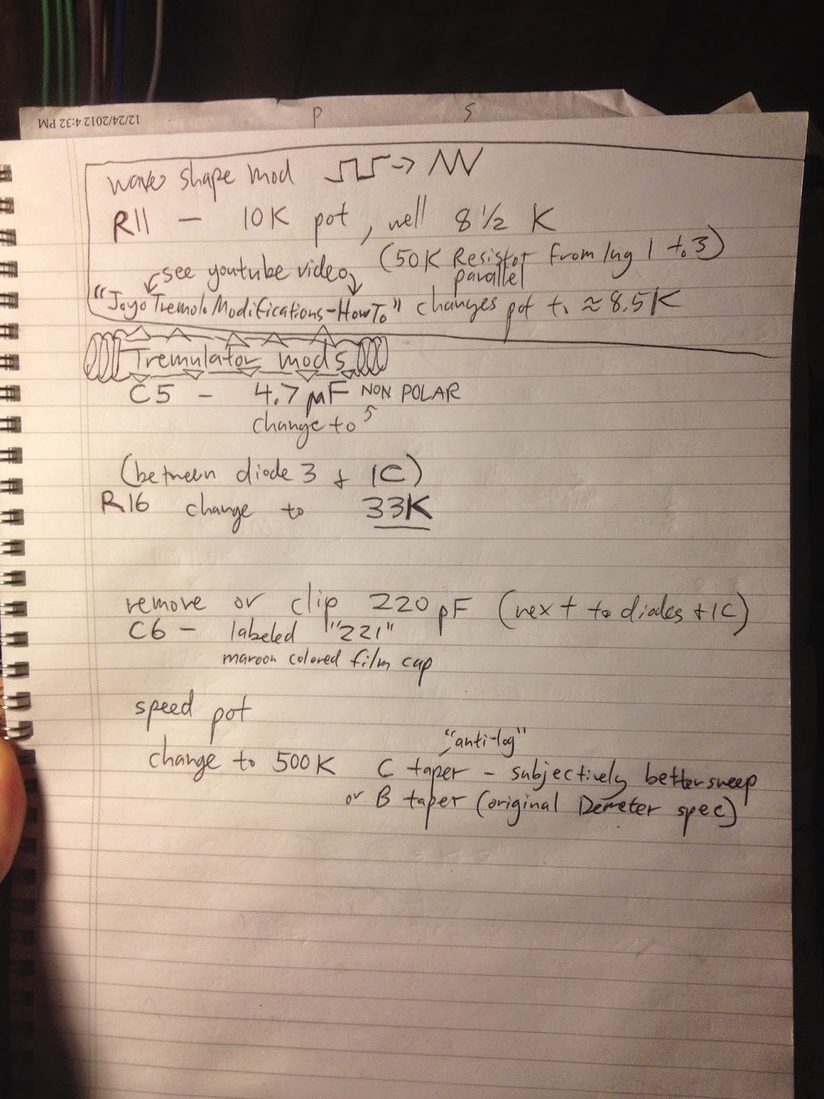
http://youtu.be/aB5xV99VXKI He also has a square to triangle wave shape pot mod that I skipped.  I found one more improvement on his mods as well, he didn't change the rate pot to Demeter value.  Without this mod the rate pot has a very bad range.

MOD LIST:
C5 - Change to 4.7 uF **non-polar**
R16 - change to 33K
C6 - remove 220pF cap
Rate Pot - change to 500K B or C taper
Optoisolator Bias Trim Pot - adjust to deepest setting for full silence on maximum intensity.  Or back it off if you like that gentle sound.  I like the dramatic deeper one, sounds more like a Tremulator to me.

R16 is right between diode 3 and the IC next to it.

C6 is the maroon colored film cap code "221" next to the diodes.

C taper, Anti-Log, is a really good sweep on the rate knob.  B taper, linear, is Demeter spec and would probably be fine too, I used C.  So did Bajaman on his Trembulator.

I also had to drill around the power jack a bit to enlarge the hole since my rate pot was a bit thick and moved things around slightly when reassembled.

And then I put some fancy Demeter/Marshall style knobs, looks great sounds great!  I built a Tremulator from scratch, gave it to a friend, have missed it ever since, finally got one back in my collection for minimum investment...very satisfying.  And that's a cool mean dog graphic too.


Monday, March 2, 2015

diy SPEAKER SWITCHER / MONITOR CONTROLLER / LINE SELECTOR #1

I have been building some really good guitar FX lately but I'll blog those later maybe, especially the Klon research I've been doing is of interest.  But this fun and rewarding little project just came off the bench:

I was looking at the Hosa and Coleman line selectors but they were dissatisfying for a few reasons: price, build quality, form factor.  So I decided to knock together one of my own.

I got a single deck 4P3T rotary switch from eBay, from China, and it's pretty nice.  This is the most essential part of the project.  With the knob attached, it shifts very smoothly from one position to the next, no clunky or harsh feel.  So far the switch is feels reliable, and it's noiseless.

Basically the 4 poles of the switch are attached to a common pair of TRS jacks (yellow wire, Left Tip, blue wire Left Ring, orange wire Right Tip, grey wire Right Ring) and all the grounds are through the chassis.  Rotating the switch sends the balanced TRS pair to A, B, or C pairs of 1/4" TRS jacks.  You can use this 3-in to 1-out, or vice versa 3-outs from 1-in.  Right now I'm using it as an input selector.  DAC #1, DAC #2, and Mackie Mixer is #3 routed through the switch into my speaker setup.  It would work equally well for switching powered monitor pairs, or what have you.

The spacing in the enclousure was a bit tight with these open frame jacks, it would have probably been best to use all enclosed black type ones, or to measure and lay it out better before drilling.  I was just emptying out my parts bin and I used every stereo jack I had left.  With a modicum of organization and care, the wiring was fairly straightforward, and I did a lot of double checking as I went along.  This is not a difficult project.

You might want to use a plastic jack with no ground connection to isolate all the grounds.  But I am not getting any ground loop noise with my setup.  I figure I'll lift grounds inside the cable plugs if that ever comes up.  I was pleasantly surprised that I don't have to yet.  Quiet like the mouse.

A very useful little project that can be used for any number of common studio audio routing tasks.  Indispensable!  Neato!  Gee Whiz! And check out that cool vintage knob!


Saturday, February 21, 2015

DIY Keeley/BOSS DS-1 Ultra - All Seeing Eye mod!!! (Disambiguation)

I am a bit fanatical about the DS-1 pedal all the sudden.  They kept sending me made in Japan and made in Taiwan models with the rare diodes and op amps, that just sound great.  But finally they sent one with the shitty Mitsubishi op amp so it's time to do the Keeley mod.

This post is a disambiguation.  There are a lot of online "tutorials" bout how to do this Keeley mod yourself, but there's a lot of vague information about the clipping modes.

After an afternoon and evening of sleuthing and experimentation let me say this.  The "SEEING EYE" mod is simply replacing one of the stock dioes with a 3mm LED which is visible on the "TONE" word on the case, you drill it out with a 1/8" bit, and glue it in, and that's the SEEING EYE mod.

The ULTRA mod is the switched part.  With the switch in the "up" position this second diode is the stock diode, a 1N4148.  The "all seeing eye" glows brightly, and the sound is very similar to the standard BOSS DS-1 tone, but with Keeley's wonderful refinements.  When the switch is down, you put a second 3mm LED in series with the stock 4148 diode, for the "ULTRA" mode.  The Ultra mode is the down switch position and there is a diode in series with an LED for the second clipping diode only.  Along with the standard Seeing Eye mod.  The Seeing Eye glows less brightly in this down switch position.  The sound is much, much louder and the clipping is reduced, along with more bass frequencies being heard.

So to wrap it up, the first diode is permanently replaced with the Seeing Eye 3mm LED in the TONE text, and the second diode is replaced with a switching array that allows to you to go between the regular stock 4148 diode.  And a second position (down) which gives the Ultra mode of a 4148 diode in series with a 3mm LED which is not visible, it exists inside the case.

This is a wonderful modification for the shitty newer $20-30 DS-1 you can find used with the annoying sound.  The older Japan and Taiwan models with the Toshiba op amps should not be modified, they sound wonderful.  But with this Keeley setup, the newer DS-1 can sound each bit as good.  I especially like the Seeing Eye mode.  The Ultra mode is a bit off-base from how a DS-1 usually sounds, so I will have to find a use for it.  I am guessing it could prove useful as a bass guitar distortion.  The Seeing Eye mode is more of a general refinement of the stock DS-1 sound.

You can see my photos below for the pedal I modified, and the full list of Keeley mod instructions on a piece of notebook paper.  I also would recommend trying an older Japanese style DS-1.  I would also recommend the Wampler mods that are available online in instructional form.  I did the "JCM" and "18 Watt Marshall" mods and they are both pretty cool.  Now I have to pick a favorite!  Or not... I have 5 orange pedals sitting here now! 


Wednesday, February 11, 2015

Alesis 3630 modification. Is it good? Or the worst ever?

I picked up an Alesis 3630 for $24 on eBay.  I have heard so much about them I had to get to the bottom of it myself.  Also, Billy Corgan used it in his guitar rig on the huge sounding Mellon Collie and the Infinite Sadness, and Daft Punk as a master compressor on their huge sounding albums Homework and Discovery.  So there could be something to it...

The first "mod" is to get a 2 Amp power supply (wall wart) I hear that the original ones are quite wimpy.  This part was about $18.

The second mod is to replace the caps in the power section.  This is where I ran into trouble.  I used 2,200 uF caps in all four position, but then one of them exploded.  I replaced it and it exploded a second time!  This was terrifying and disheartening.  I have heard of this phenomenon but this is my first time encountering it.  I believe that 2,200 uF was far to big a value for C2 and C3, and they were probably drawing too much power.  So I replaced them with 220 uF caps (C2, C3) and C4 and C5 I returned back to their original 1000 uF value.  I was too nervous to try 2,200 uF in there again.

So I cleaned up the mess, replaced a ceramic cap that got shattered (!!) in the first explosion, and let it run for an hour and a half.  This was nerve wracking, I kept expecting more popping caps.  After about two hours I felt OK to put it back together and start passing audio.

Let me mention the first nightmare.  When I pulled the knobs off for the initial disassembly, about 5 or 6 pot shafts got ripped out along with the knobs... nasty.  I don't know if some hapless punter glued them on or what.  So ordering replacement pots, and doing that part of the job, added a lot of extra time and work to this apparently ridiculous project.

The audio quad op amps that came stock were a respectable TL084CN (earlier revisions had much worse).  But I had to see what all the upgrade fuss was about so I installed sockets and a pair of Burr Brown OPA4227PA.  The two of them cost me about $5 on eBay.  So now my total investment in this 3630, including pots, is around $50.  Not bad.

I also replaced C16 and I think C33? (the other side of the board) with Panasonic electrolytic caps, since they are in the audio path.

Removing those caps gave me a little room for the nasty part, which was ripping apart the quad op amps with angled cutters.  Once you get one half of the op amp's legs snipped, you can just wiggle it back and forth a bit and then the other half of the legs will break eventually.  After this, pull the legs out with a soldering iron and some tweezers or grabber of some sort.  Then you can clean up the holes with desoldering braid (and a very hot soldering iron).  Once the holes are nice and open, you can put in a socket.  Then you can put in your new C16/C33.  After all this brute nastiness, now it's time to gently slide in the Burr Brown op amps... ahh....

Another word of caution.  I think the ribbon cable leading to the LED meters could be kind of delicate so be careful.  My left side gain reduction meter doesn't work any more.  I don't know why, but maybe I was rough on the ribbon.

The 1/4" jacks also needed a heavy dose of contact cleaner, and I refreshed the solder points for good measure.  I was getting some audio glitches from here but not after the cleaning.

I don't know which was more disgusting to work on, the Alesis 3630, or the Behringer MDX2100 Composer.  Both pretty revolting.  But in the end, they are both nice compressors to have working in the rack.

How does it sound?  Dirty-six-dirty is about right.  You get this kind of cassette tape, gritty, slightly dark on top, sort of big on the bottom thing.  Think Daft Punk, or Mellon Collie guitars.  Things sound a bit bulbous and sort of cartoon-like, a little low-fi or fuzz around the edges.  Which can be a useful sound, to my ears.  The Composer is a lot crisper and cleaner.  Honestly it wasn't that bad pre-mod either.  By the way--If you own an earlier '90s pre-Rev D. model, you might have to add a couple caps in the detector circuit, you can google this mod.  Mine already had them.  You can also snip some jumpers to take the gate out of the circuit and clean up the sound, but I didn't do this, I guess I wanted it 'kind of stock'.  And if you've got an early one with a comparator IC as one of the quads, that should be replaced with an op amp as well.

This sounds nothing like a DBX.  The compressor's action is not so defined or obvious, or quick I guess.  The attack and release, ratio controls are also not as responsive as I'm used to hearing in other compressors.  You can really smash the gain reduction meters, it seems a lot of people use 3630 like this.

It's too early to tell how much I'll use this, but it has a flattering sound that can work great for fattening up a thin sounding fuzz bass, for example.  I'm sure it would work great in a live-instrument rack, too.

Worst compressor of all time?  I doubt it.  Not bad.  I can't tell you how good it feels to be done with this one though.  I do plan to use it and it's been sounding cool so far!  The power supply lesson learned the hard way was probably worth the project alone.


Tuesday, August 5, 2014

DIY iRig Guitar to iPhone Interface

I've just finished a project I started months ago.  Here's a working layout for the IK iRig version 1 for iPhone or iPad.  I am going to use my iphone as a strobe tuner for guitar and bass setups, and for recording demo songs on trips and such.  The main advantage of me building this rather than buying it, is my construction is a lot more robust than the plastic IK unit, and I used switchcraft jacks, star quad cable, etc.  Between this, and my two Tascam iPhone interfaces (line input, and stereo XY mic) I'm covered for portable audio.  Amazing.

In use, with IK's free Fender and Marshall Amplitube apps, there is noticeable latency when playing guitar, but it's tolerable.  Also, this iRig circuit is pretty noisy, and the output is pretty low.  Thankfully IK includes a noise filter as one of the selectable effects in the Marshall app.  The sound quality of Amplitube is harsh and gritty, but, it'll do fine for jamming, writing, or demo recording.  I would not use it for critical recording.

Here is some technical information:

http://www.danacsimmons.com/content/working-iphone-audio-input

And here's the schematic, my stripboard layout, and my finished unit.


UPDATE - REBUILD ON 5-23-20

I was having some problems with my phone and my old build.  I decided rather than to troubleshoot I would rebuild in a new enclosure.  I re-used the circuit, though.  New TRRS cable, new enclosure.

It didn't work right away.  The two problems I found (d'oh!) were not sanding the paint off where the audio jacks touch the enclosure for grounding, and also had to spray some contact cleaner into the headphone/mic jack of the iPhone.  Once I did those two things it now works perfectly, very reliable, no weird cut outs, noise, etc.

Really obvious stuff.  Make sure your grounds are actually grounds.  Make sure your connections are all clean and reliable.  Had to sleep on it, but solved it quickly the next morning.

Also, some people are using the J201, or the 2N5457 in place of the BC245C.  You would have to mind your pinout (drain source and gate pins).  There are reports of different gain levels with these substitutions.  I haven't tested them.  They might be easier to find than the BC245C.

Also noticed my iphone is putting out about 0.88 V to the FET, not 2.7 V.  But it still works fine.

Here's the new re-build:


Sunday, June 8, 2014

"Nigel" quad reamp and 24 channel summing mixer

This was a fun and laborious project, the offboard wiring was pretty intense, there's just a lot going on.  I still need to finish the last two DB25 snakes.  I used Edcor transformers, DB25 summing PCBs from the GroupDIY White Market, shipped from the UK, and a Par-Metal enclosure, along with Neutrik jacks.  My switches are a little cheapy but they basically work.

It's a 24 channel Folcrom-style analog summing mixer, the last 8 channels can be switched out when not in use, so down to just 16 channels, to minimize crosstalk.  Make up gain is provided by a stereo pair of mic preamps, any of your choice.

The outputs are switchable between Edcor trasformers, or 100uF Silmic II capacitors bypassed with small Wima caps for a little cleaner sound.

The unshielded transformers do not like to be close to the computer or other power supplies, but other than that they can be very quiet.  The Edcor transformers have a really nice sound, kind of "vintage."  The capacitors are quiet in any scenario.

The reamps are switchable between unbalanced 1/4" for standard re-amping, and balanced mic-level XLR for running into preamps for extra coloration of tracks, an idea I took from  Peterson Goodwyn, using H-pads.  Grounds can be lifted on the input, and there is RF filtering copied from the Jensen reamp schematic.

I used 6.8K resistors on the summing mixer inputs and other values for the 4 mono channels, see DIY Recording Equipment article for the math.  I went for about a 150 ohm output impedance when calculating the shunt resistor values.  The output Z climbs slightly to 160something when switched down to 16 channels.  I thought 4 mono channels was right for kick, snare, bass, and lead vocal, the rest of the inputs are L and R pairs for panned tracks or stereo busses.

My short review is, for rock music especially, or anything with lots of tracks, the summing mixer does indeed provide extra space and depth, dimension, to the sound vs the flat clean sound of DAW summing.  I'm all about it.  The analog summing section itself does something too that does not happen with just running a pair of preamps on a DAW summed mix, you can hear it.  The slight complication of setting up the mixdown is absolutely worth it for the sound.  The transformer vs capacitor output was a good design choice, as I prefer either one based on the program material.  I like the transformer for a little midrangier sound, with slightly rolled off high and low exteremes, and a little color.  I like the capacitor output for a very clean sound with deep sub bass.

When I plugged it in and listened to it on a rock band mix I had done, I knew that analog mixing was something of a missing link for me.  Just a little extra spice that helps things "fit together" in a pleasant way, sort of a picture frame around your careful mixing work.  It won't make or break a mix but I like the subtle detail it adds.  I cannot wait to add hardware EQ and compression to the stereo bus.  In the mean time Waves NLS and software comp/EQ are good stand-ins.  I really am curious to see what a real full-on mixing board will do now.  I've got my eyes on the Allen and Heath ZED series by the end of the year.


ADDITIONAL INFO AND DETAIL


Preliminary diagrams/not used.  The one on top is the idea to use a 10K:10K line input transformer on every channel of the summing mixer.  I decided not to do this, the wiring, and cost, would have been outrageous.  I decided to get my mojo on the outputs using only a pair, which is what the second two diagrams are attempting to do.

Also if you look at the small handwriting you will see a list of more expensive and fancier transformers you could use instead of the cheap but decent Edcor.  These would be low impedance output mic matching transformers I think anywhere from 200:200 to 600:600 would probably work.  Not all manufacturers use the same impedance for this type of transformer.  I end up using the capacitor output most of the time anyway, and get my transformer sound from the make up gain preamps.  The 600:600 Edcor just offers "more color" if needed.  Kind of sounds "Vintage."  NOTE: I did not use any of these diagrams it was just brainstorming.  See below for what I think I did.


Here is the output section.  I'm super paranoid about phantom power so I used capacitors when bypassing the transformers.  Use two 4PDT switches, one to route the inputs of the transformers/caps from the summing mixer, and the other switch to rout the outputs of the transformers/caps to the XLR jacks.  Since this signal is balanced the caps are configured in +/- pairs to work in place of the transformers.  The transformers are 600:600 Edcors but there are many others that would work.  The caps are 100 uF Elna Silmic II bypassed with .01 uF Wima film caps (parallel wiring).  You can probably play with these values too, or even skip the small bypass caps altogether.  I was just sort of copying Jeff Steiger's VP312DI coupling cap arrangement.  The necessity of the small cap is debatable.  I find that these values and brands sound very good in real world use.


Here is the basic reamp idea of the Nigel.  Basically the ground lift scheme is from the Jensen reamp schematic which is much easier to read than this scribbling.  I also added an XLR output on a switch that uses an H-Pad to drop about 36 decibels, you can find calculators for the resistor values on Google search.


Edcor 600:600 transformer.


Elna Silmic II 100 uF capacitors bypassed with .01 uF Wima capacitors in parallel.  I think 100 uF is flat enough with the low impedance output to extend very low in frequency before any roll off.  I have not run it through a scope, but it certainly sounds plenty deep and low, much more so than the transformers.


This is the reamp section, I did 2 channels on each perfboard.  2 boards for a total of 4 channels.  The toggle switches between Hi-Z instrument level output (TS jack) and mic level output (XLR).  You can see the shapes of  the L-pad (TS jack) copied from DIY Recording's reamp unit, and the shape in sort of an H or a spider/crab shape of the H-Pad for the XLR output that I calculated.  The transformer is in the signal path on both jacks, the switch just changes the resistor pad networks along with balancing/unbalancing for the appropriate jacks.  Be sure to take into account the signal drop across the transformer when calculating pad values.


Reamp inputs with ground lift.  A plastic TRS jack is required to be able to lift the ground.  A metal jack will automatically be physically coupled to the chassis on the sleeve just by tightening it down, so plastic is needed here.


Here is a simple DC-blocking capacitor coupled Line 2 Mic Pad in a standalone box that you could use to run a stereo mix output into a pair of preamps.  It's not a summing mixer but it does give some extra color.  I used Vishay BC Blue 100uF electrolytic capacitors, and .01 uF worth of polystyrene caps in parallel/bypass.

BHL Phono Preamp / WAC -49- #2 with Pyramid capacitors

I built another one of these using basically the same design...see my older post for the layout and general plans if you want to do one.  This time I used vintage USA Pyramid paper-in-oil capacitors for the 1 uF coupling caps.  The sound is even fatter and smoother than the standard Russian caps.  Ever so slightly, of course, but I appreciate the difference.  I think cap choice makes a pretty big difference in a preamp like this, I've read other builders say the same.  One guy used cheap panasonic film caps I think and it didn't sound as good to him.  This is no place to skimp when buying parts.  After all, this is an audiophile piece of equipment.  I had to sand the leads on the big caps clean because there was wax and junk all over them.  They soldered up fine, and work perfectly, despite their old age.  The best part is how cool they look, obviously, and the nasty wax coating that's all over them.

The other difference this time around is I used 100 uF bypass caps on all four JFETs, in parallel with the 50 ohm resistors.  The output is nice and high and easily matches a CD or MP3 of the same material in volume.  I would say that this is an essential modification to the stock BHL unit, I don't know why he didn't design his kits with more volume.  The level with no bypass capacitors in place is just not adequate.  The nice part about working on stripboard like this is it's easy to fit new parts like that, although a redesigned layout with the 100 uF caps specifically placed would probably be more elegant and not so tight.

This thing truly sounds great, and is very quiet.  The next step will be to build a dedicated 20-30 volt regulated DC power supply, and to finally ditch the old Technics direct drive for a better turntable.  I've got my eye on the Audio Technica LP1240 and various Shure and AT cartridges.

I gave the old one to a friend in need.  Things are sounding good in here.


Wednesday, March 19, 2014

Technics SB-LX30 speaker mods, stage 1

I found this post ages ago in 2001 when I was starting college http://www.enjoythemusic.com/under200speakers.htm about the good value of the Technics SB-LX30 speakers.  I went for the big ones for the BASS, you know.  They've been in so many rooms, houses, cities, and states by now, sometimes used and not, and in 2014 I finally started the modification process.  These speakers really bring my turntable to life and make me want to buy more vinyl records..

Rather than just using Dynamat, I added three internal braces, cutting a 1 1/2" dowel from Lowes to fit the internal dimensions, and gluing in place with Titebond, and also drilling and fixing with wood screws.  This serves to stop the rather large and somewhat thin particle board cabinet from resonating.  You can easily hear the before and after effect by thumping the cabinet with your finger.  I also used a little Dynamat where needed on the larger surfaces that weren't close to my braces.  I could use a little more on the top and bottom.  I used a 12x12" Dynamat sheet per speaker.

Then I stuffed in some Polyfil from Wal Mart, and re-connected the woofer and tweeter.  The sound is definitely tight and controlled now.  I used half a bag of "quilting" Polyfil per speaker, a single bag was enough for both cabinets for my purposes.

Stage 2, eventually, will be buying a new woofer and tweeter from parts-express.com and adding a high end crossover and thicker internal wiring, and thicker wiring from the amplifier to the speakers, which are now mounted high on a wall, on shelves I built from Lowes shelving board and shelf braces, and sitting on some foam for acousic decoupling.  But for now I'm kicking out the jams in style.  The stage 1 modified Technics are solid sounding speakers, plain yet tasty, in my medium small sized room.  Actually, I might leave them how they are since the bass is so tight and thick!  Scour ebay for a pair of these if you will and get to drilling!


Tuesday, February 11, 2014

Dantone/WAC "C12" clones

Here's a pair of C12 "clones" I just finished which you can read about here: http://www.gearslutz.com/board/so-much-gear-so-little-time/903043-i-just-wanna-show-off-my-c12s-i-built.html  I am not sure what to call my "company."  These mics sound fantastic.


REAMP with schematic

Here's a "reamp" I built for a friend.  I'll be doing more, including a stereo "Amp /OR/ Mic Preamp (balanced)" version for myself.  If you can follow this badly drawn schematic on note paper, that's what I used.  I took most of my tips from Peterson Goodwyn's LINE 2 AMP and LINE 2 PRE devices on diyrecordingequipment.com, he's got some great articles posted.  The balanced input jack must not be metal, grounded to the chassis, that is, because you want to be able to lift the ground with a switch if necessary for noise/ground loop isolation.  I used the Jensen reamp schematic which you can find on their website, for the RC to ground in lift position, which helps with radio frequency noise rejection.  The transformer is an unshielded 10K:600R Edcor that was an !excellent! value and really does sound fantastic.  You might need to keep it away from large guitar amp transformers, etc, in use to minimise noise.  A fancier Jensen, Cinemag etc. that has mu-metal shielding, in a can, would obviously be ideal but I wanted to save money.  I think this entire project was about $20, give or take.  You could use an XLR input, but I wanted a 1/4" since my friend will probably be using an unbalanced 1/4" line output from his mixer into this Reamp.  To save him from having to use a special cable, any 1/4" instrument cable will work with the TRS input, it will just short the "cold" signal, or that end of the transformer primary, to ground, which is fine.  Obviously you can adjust the output impedance by tweaking the 15K series output resistor, or use a pot there to get real tweaky (as in the Jensen).  You want to be in the neighborhood of a guitar or bass pickup.  You could also wire up an output attenuation pot like Jensen did but I wanted to keep it simple.  New York Dave also posted an article with a similar reamp to look at.  Another idea is to use a lower ratio transformer if you want a hotter output.  You just want to get the output impedance to simulate a typical instrument, and the input to properly load a line output, along with knocking down the level a bit.  Peterson really explains this well on his website and on Youtube.


Wednesday, June 5, 2013

Korg Monotribe noise mute modification


If you send this contact to a switch, and connect the other end of the switch to a ground point, you can mute the noise.  What I was not expecting is this also mutes the hi-hat, and the snare noise, so all you're left with on the drum sound is a low thud (the kick) and a slightly higher thud (what's left of the snare).

I don't know how useful this mod is, it was a bit of an experiment.  You can quickly toggle the noise on an off to musical effect, stutter.  You can also toggle away the hats, snare noise to thud-ify your drum beat, to musical effect, sort of a "drop."  Kind of cool, time will tell how much I use this switch.  I kind of like musical moments like these.  When I pull back the noise on a drum loop I am reminded of certain Radiohead moments.