Saturday, November 14, 2015

Fulltone OCD Version and Mod Notes. PEDAL DIY.

I hated this pedal for a long time, but I've recorded a guy that used it to get some amazing big-amp tones on a heavier project.  Something about going around to older, disused pedals and either fixing them up, modifying them, putting them to work, I have rediscovered a few gems in my collection that I've criminally overlooked.

First of all, the vintage-spec MXR Distortion+ is a pretty nasty distortion on guitar, very crude.  But that same exact crudeness makes it a standout on synthesizers and drum machines.  For electronic instruments you often want a flatter response with a lot more bass and treble than you would on a guitar.  The tone shaping is not as desirable.  Anyway if you're looking for an overdrive for your acid licks or whatever, give the Distortion+ a try, they're cheap, they are also easy to build yourself.

Next up was the Fulltone OCD.  I built Harald Sabro Bolstad's "Version 3" but I've come to believe the layout is actually a late-version-3 or an early-version-4, maybe some sort of transitional schematic, because it has the germanium diode in the clipping section.  Which is exactly the reason I hated the pedal.

By simply removing the diode and using a symmetrical mosfet clipping pair, as in the earlier, and later, OCD versions, you get a much better feel and response.

If you own your own authentic Fulltone OCD and it has the diode, this would be a very simple mod.  Just desolder it, clip it out, and add a jumper wire in its place.  There's another blog who claims good results from this mod.

I find the tone of asymmetrical diode clipping, in general, very hard to swallow.  This is ultimately the reason I keep abandoning the Boss SD-1 every time I try it.  It does something to the transient of the guitar attack and makes it sound very blunt and hard.  The symmetrical clipping option gives a much smoother, more natural response which also has a little more sparkle on top.  Overall, it just sounds way more transparent and I recommend it hands-down.

I'm a geek so I added the diode on a toggle switch on the side of the pedal labeled "V3 V4."  Who knows, it just seemed like a cool idea.  Maybe I'll use it some fateful day.  Right now the switch is in V3 position and I'm not moving it.

I have heard rumours that the later V4 pedals have a different tone section which removes some bass response.  I have not been able to find any schematics like this.  The tonal changes along with potentiometer taper and values has continued on into a 5th, 6th, maybe even 7th (current?) version.  I haven't had the opportunity to try those.  They are also undocumented on DIY websites.  You just have to buy one I guess.

I just like the almost too-fat marshally kind of tone from this V3.  I'm a sucker for big bass.  Also I wrote "Rico" inside the pedal  just to increase the value, LOL.  Seriously people pay more for those on eBay.

One last thing I noticed is the stock OCD has a pretty bad 60 Hz hum when engaged, even with the guitar turned all the way down.  It's louder than any other fuzz or boost on my board.  I added a 100 uF filter cap from +9V to ground, which decreased the noise to a level comparable with my Meathead Deluxe.  I'm happy enough with that.

Not being happy to leave well enough alone, I went ahead and added a "Power Boost" DC jack onto the pedal which internally doubles the input voltage to about 18 volts, no special adapters required... cool!  I used Iviark's "simple voltage doubler" also known as a charge pump and I'll post the diagram of my power switching below.

I have maybe 4 or 6 pedals that can run on 18V and I almost unanimously prefer them in that setting.  They seem to be a little louder, and a little flatter frequency response with truer highs and lows.  So I run the OCD in the Power Boost mode exclusively for now.  By the way the Colorsound Power Boost 18 Volt original version is one of the best pedals I've ever heard, which is where I nicked the name from.  Talk about a secret weapon.

By utilizing the battery contact on the standard DC pedal power jack you can make it so the charge pump switches off when you insert a supply to the normal 9V input, which ensures that under no weird circumstance could you ever plug in two power supplies at once.  Believe me, I know people that would do that.

Note: I'm sure you'll have to use a larger enclosure like this 125B or bigger if you want to include all these mods in your build.  The nano/MXR size would probably be too tight.

Mini Review:  This pedal has replaced the Tube Screamer / MXR Custom Modified Badass OD / Boss OD-3 position on my pedalboard.  I need a pedal that can go from slightly gritty clean boost, all the way up to heavy overdrive (but not a distortion, per se).  For either chimey "feel" kind of clean on the edge of breakup playing, or rocking out with dirty riffs.  I have had so much trouble finding a pedal that does these all well.  The OCD just has enough fatness and chime to get where I want, without being either too thin or too thick, and takes the spot for now.  Although the others mentioned certainly have their merits.  I am wondering if the Mad Professor Little Green Wonder might also fill this spot.  But that will be a project for another day.

DW


Friday, November 6, 2015

Russian "Civil War" Red Army Overdrive Big Muff Sovtek EH.

I used the GuitarPCB.com PCB for this build.  I also used their parts list.  Came out sounding exactly like what I'm hearing on YouTube from the vintage originals.  I used a BC549C transistor.

I tried some film caps at first, but it didn't sound right, too clear.  Then I replaced anything I could with ceramic and/or multilayer ceramic capacitors for all the coupling caps and small value caps.  The sound got a lot more nasty, mean, crude, and good with a heavy application of ceramic fidelity.

I built two of these, one of them speaks slightly more in the treble, the other is very slightly more bass oriented.  Perhaps from differences in part tolerance.  This one's going to a friend, on commission, woohoo!

What a nasty, awful fuzz tone, I love it.  Very different from, say, a Ram's Head.  I was surprised how different, actually.  Think Pulse Tour from David Gilmour as opposed to The Wall.  Also think bowel liquefying low end.  I love cramming a big circuit like this into a tiny enclosure, bonus points.

Another lazy/fast breakthrough I had is using super glue as a clear coat over the font.  It doesn't work with Sharpie markers (see fuzzy dissolved control knob names) but works just fine over any sort of paint or paint marker (the blue and purple stuff).  I spread it as thin as I could with a toothpick and it looks fine.  Way better than clear tape (shudder...don't ask).  Don't put the glue on too thick or it can peel up around the edges.  Also watch out for those fumes, ouch!


Microphone Shockmounts - it's the little things that count

In what may be the finishing touch of my (what I call them now) Dantone/WAC DW-276 microphones, I have finally arrived at a respectable shock mount, that's a lot better than the one that comes with the Apex 460.

I bought a shockmount on ebay from a seller called Q-Mic who also has a website www.q-mic.com.  The wing bolt in my hand (picture below) is what came with the mount.  It's too small, and roughly machined, so the mic never gets quite tight enough.  The mic tends to sag and fall sometimes, which drives me crazy.

My solution was to use a Pearl Wing Bolt, a piece of drum hardware I also was using in my Eliminator kick drum pedal, I had a few spares, and it fit perfectly into the shockmout, using a couple of the washers it came with.  What luck!

Now it gets super snug, "that thing ain't going anywhere" am I right?  And the contoured chrome look of it just adds that nice hint of Bling to the affair.  I'm happy.

It looks like Q Mic may have improved some of their mic mounts since I bought these, but maybe this could come in handy if you happen to own a shockmount with a crappy tension bolt on it like mine.  It seems like metalwork in general is pretty iffy on a lot of the cheaper Chinese stuff.  It's amazing what a quality $4 bolt will do.


Friday, October 23, 2015

Dan's Subkick speaker microphones

One of the most popular DIY microphone projects is the "subkick" and it's been around as long as rock and roll and spare NS10 woofers sitting around studios.  It's an easy and satisfying build.  There are probably hundreds of DIY subkicks on Google if you want to gather ideas.

First is my new Yamaha-style subkick.  I used a cheap MCM Electronics 8" woofer and mounted it in a cheap 8x5" Ludwig tom tom.  I cut away the drum head leaving about half an inch of material connected to the ring of the head.  I was able to barely slip the head over the edge of the woofer, and the little bit of plastic I left was enough to firmly hold the speaker in place, while leaving room for the speaker surround, not interfering with it.  It was a simple bit of construction and worked out pretty well.  I'll probably add a $6 Pearl mesh head to cover the rear of the shell to keep things clean.

The tom I bought came with an arm (there were several in different colors on eBay) and the base I just used a junky old snare stand I had sitting around, that lucky enough has the same diameter bass as the tom arm.  Buying the tom was the hardest part of the project for some reason.  I wanted to keep it cheap.  I paid $40 for the tom and arm, and about $10 for the speaker, which makes this a nice $50 project.

I drilled for an XLR jack on the side of the drum.  The soldering is pretty straightforward.  A speaker is backwards from a microphone diaphragm, so the (-) speaker terminal is actually the one that will be in phase.  So I wired the (-) speaker tab to pin 2 of the XLR (hot).  The (+) speaker terminal I wired to pin 1 (ground) on the XLR.  I also wired pin 1 to a wire I ran to one of the lugs to ground some of the metal in the drum, why not I guess.  Probably not strictly necessary.  Pin 3 is unconnected.  This is an unbalanced microphone but I ran into no noise issues in my testing.  You might want an inline pad if you're getting really loud, something like a Naiant or Shure XLR pad, or you could build one into the subkick.  I did not find the level to be an issue with my Mackie Onyx preamp, but I did have the gain at a conservative setting.  With an API preamp you'd probably have to engage the pad.

Here's some photos and I'll follow with the construction and technical details:


Here's the first subkick I made back in 2010, it got used on an album by Green.  Sounds very different from the new one.  This one I just attached a mic mount directly to a 6" guitar speaker, and an XLR plug, and put some burlap fabric (acoustically porous) over the front to protect the speaker.


SOUND TEST


Here are two sound clips of the subkicks on the same drum, a 22" Pearl Export, which was not tuned (!) between takes.


I think you will hear that they sound drastically different, even though the drum tuning and setup is identical.

The answer is in this article from Sound on Sound:


Here's the gist of it in a quote, 

"Returning to the Subkick idea, basically what is on offer is a relatively high-mass diaphragm (cone) with a huge copper coil glued on the back, adding more mass and inertia. The whole assembly is horrendously under-damped and almost completely uncontrolled. Not surprisingly, when employed as a microphone it has what under normal circumstances would be an appalling frequency response, completely lacking in high-end. What is important, though, is the very poor damping, because this means that the diaphragm (cone) will tend to vibrate at its own natural resonant frequency when stimulated by a passing gust of wind — such as you get from a kick drum. So really, the Subkick isn’t capturing the kick drum’s mystical subsonic LF at all — it’s basically generating its own sound. In other words, what we actually have is an air-actuated sound synthesizer, not an accurate microphone!"

So what you're hearing is the tone of the speaker at its resonant frequency, more than the actual sound of the drum.  This is not an accurate microphone in any way, more of a bass resonator.  I think listening to my two files will show you how much of the speaker you're hearing and how little of the actual drum.  Pro Tip: Hold the woofer up next to your ear and gently tap the cone.  You will hear a low note ring out, and this is what you're roughly going to end up with when you build your subkick.  You could use this "tapping" method to select a driver that sounds kind of how you want before attempting a build.

Acoustically speaking, the smaller guitar speaker resonates around 80-100 Hz, as you can see in the first Pro Q2 screenshot below.  Subjectively speaking, it's got a little less sustain, and a little more high frequency information, such as the click of the beater around 1K.  If you load these files into your DAW and use something like Pro Q2 with a band-listen function, it's really informative to sweep around these sound clips and hear whats going on at different frequencies in isolation.

The big tom tom subkick puts across a much bigger "sub" sound, resonating at 60-ish Hz, with tons of information below that in the subs, and very, very little coming through in the midrange or top end.  I hear a little more sustain to this one, which I attribute to the softer rubber surround on the speaker, as opposed to the stiffer paper surround of the guitar speaker.

So you've got two very different subkicks which I both think have usable sound.  Every subkick is going to sound different and that's fine.  Recording Hacks has a good shootout that will show this to be true too http://recordinghacks.com/2012/02/05/moon-mic-review/  Although I have to say, right now I'm very pleased with how the big blue one came out.  It just looks impressive in person, people say "wow!" and I can't argue with the big low end.  I think I'd rather set up a subkick than use an LF synthesizer like Max Bass, but those are fine too and something you can always pull up no matter what mics you tracked.


Fender speaker subkick:


MCM speaker / Ludwig tom subkick:


Tuesday, August 18, 2015

Modding the ProCo Rat and Turbo Rat

I suppose I have a bit of history with the RAT, I've used it since my first band, on various key songs, and have owned several throughout the years.  At this point I have a Vintage Rat, Turbo Rat, and You Dirty Rat, the first two have been modified.

The first, easy enough mod is to replace whatever op amp you've got with an LM308 if yours is a newer version.  The LM308 has a slower slew rate and a generally darker, nastier sound than the newer versions.  It is the original spec'd op amp from the vintage Rats, which was changed out for something else in the 2000s.

The second, fun mod is to add clipping options.  In both my Turbo Rat and my Vintage Rat I have a DPDT switch with two antiparallel clipping diodes selectable on the toggle, either LED or 1N914.  This gives you higher or lower headroom, which really helps with high output or lower output guitars, sort of like the Fulltone OCD's hi/lo switch.  In the case of the Turbo rat, it gives you the standard turbo mode (5MM LEDs) and the Rat 2 mode (small signal silicone diodes).  My review of the Turbo Rat is that 5MM LED clipping is a bit heavy and severe for most of my uses, so I find it a lot more useful with the 1N914 mode, which puts it very much in the Rat 2 kind of sound camp.  The 5MM LED has more than twice the forward voltage of the 1N4148/1N914 diodes.  

These pedals are all very closely related, with the main differences being the clipping diode selection.  The Vintage Rat does have more of a smooth compressed midrange character, where the Rat 2 and Turbo Rat have more of an open, clear sound that's nice as well.  These differences occur in the circuitry that is not the clipping diodes, so I'm glad I have both.  Just depends on my mood which I want to use more.

There is a new Rat out called the Fat Rat with a MOSFET clipping option I think, I have not tried that one yet.

There is also the Ruest Rat mod, to get more bass out of these pedals.  I ended up not liking that mod, and removed it.  If I need a big bass sound I will use something else entirely.  To me, the Rat is all about midrange and cutting clarity.  It's that '80s thing, yo.

Other various mods to all of these pedals have been standard Boss style 9-volt jacks (why ProCo, why), adding an LED along with a 3PDT footwsitch to the Vintage Rat, and hammering the steel enclosure.

 The enclosures are pretty poorly designed in my opinion.  The top surface is too thin, it can be bent by stomping enthusiastically.  My turbo rat needed to be bent with pliers and hammered back into a flat shape.  The circuit board was actually bending since these pedals are pot/switch mounted on the PCB directly to the enclosure.  Bad design choice, the PCB could eventually crack.  Also the "fins" of the bottom piece leave a gap between the top where dust and filth can creep inside the pedal from the cracks on the side.  I had to fix this with more hammering and bending.  I was able to close the gap considerably on my Turbo Rat.  My "You Dirty Rat" still has a gap as I have not messed with it yet.

Here's a picture of my Turbo Rat being modified.  The DPDT switch was not the best idea, it's very tight in this small enclosure with the PCB mounted.  It probably would have been better to use an SPDT for the diode mod.  Make sure you use the correct pads on the PCB for the two wires from the clipping mod switch.  There are 6 or more pads and you need to pick the ones that aren't connected.  I guess this proves they use the same exact PCB for the various Rat models and just mount different sized clipping diodes to the PCB with the various hole spacing.  Along with possibly other component variations.

The rat.  A nice hangover from the '80s that I'm happy to wake up to.


Tuesday, June 2, 2015

Reducing Monotribe Clicks and Pops

I was playing the Monotribe with a MIDI keyboard, which is a lot of fun, but the nasty clicks and pops during the note on and off are total dealbreakers when the 'tribe is plugged into a big bass amplifier, or your speakers are cranked up.  It's not so much an issue in most sequences, but when you play it like a keyboard instrument, it's a pretty glaring awful sound.

So I watched THIS YOUTUBE VIDEO and figured out what to do.  Basically I soldered a 4.7 uF capacitor from the base (pin 1) of Q24 to a ground pad (negative cap leg to ground).  He suggests you can use a 1 uF all the way up to 10 uF depending on your preference.

The trade off is it does seem to soften the envelope a bit.  It sounds a bit less snappy, so I might go back in and put this mod on a switch.  The volume envelope sounds a little bit compressed now, which tames the acid edge perhaps a bit much.  Of course you can still get the filter screaming or whatever.  But I recommend a switch.

The mod really does work well, the clicks are almost completely eliminated, which makes the monotribe now a joy to play as a monophonic keyboard instrument (see: MIDI mod in an earlier post).

If you haven't cranked this thing up through a guitar or bass amp, you've got to hear it.

Here's the transistor pinout for Q24:


And here's the best picture I could get of my cap soldered in place.  I would recommend cutting the leads to the right length, and tinning them with solder, before installing the cap.  Do the transistor connection last, and as quickly as possible to avoid damaging the part.  Tinning the capacitor's legs helps here because you only need that tiny bit of solder to make that tiny connection, and it frees up a hand to help position the parts.  It really wasn't that bad of a task.  It came together quite easily with the right technique.


Monday, June 1, 2015

'Lil Speaker Thang, a portable DIY boom box, Logitech X-230

Ok reusing some parts.  I had this old Logitech X-230 subwoofer/amplifier sitting around for a long time without the correct remote I/O and volume unit to have it working.  I googled it and some folks had wiring pinouts and such posted, this was a popular model.  

I took a 9-pin DSUB computer monitor cable, cut off the female end, secured it to my recycled enclosure, and soldered the various wires to: The audio in to RCA jacks, and the amplifier outs to speaker terminals.  A10K stereo volume potentiometer is used to trim the input levels.  Amplifier ground, audio ground, are connected inside my enclosure.  And a little SPDT toggle is used to connect the two wires that give it power.  Maybe you could call these connections "5V" and "Power On/In".  The correct DSUB pinout for the subwoofer is in the image below.

I didn't bother with the status LED wire since the sub never truly turns off.  The power is just sort of a "standby" switch and you can obviously tell when it's turned on--you hear it hissing or passing audio.

The enclosure is a trashy speaker selector that I got from eBay China, that didn't work reliably, so it's being recycled.  You could use any small project box for this.  Its speaker terminals were re-usable and it's a nice solid box at least, even if it used to be an unreliable speaker switcher.  It's nice to get use out of things instead of having to throw them away.  The speaker wire is recycled too, some nasty old skinny cable that was lying around a bit tarnished, but for this application I'm not too bothered with fidelity, since the whole system is pretty lo-fi.  I soldered the speaker cables to the little cube speakers.  Since I'm using standard speaker terminals, I can connect just about any type of standard passive speaker to this amp.  I wonder how well it would drive some of my bigger speakers?

After some mild troubleshooting, it worked wonderfully.  The cube speakers are some leftover bottom shelf ones from my brother's old computer.  In this context they really don't sound so bad.  When paired with a bluetooth audio receiver, this is a fun little system to setup in whatever room and stream phone tunes.  I might use it as monitors for mobile recording (along with headphones).  Or bring it to the beach.  Or as a remote monitoring system for recording around the house, or the electronic drums.  Sort of a tiny grot box PA.

What a somewhat complicated yet satisfying project!  It's not worth anything or the time I spent on it in dollars, but it's a great little thing to have.  I've always wanted a little rig like this, since the last album I recorded for Green.  We were using little computer speakers in a big warehouse to check takes on.  Tiny speakers in an enourmous room.  Mainly due to portability.  So now I've got one.  And it looks cool... of course you can't beat the all black finish either. :-D


This was the correct wiring scheme:

Here is a picture to use to help wiring the 10K stereo volume potentiometer.  I do not trust the power switch section of this diagram, I used the scheme described above.  This is just sort of to show you how the volume pots are connected to the input jack, and then out to the DSUB.  I found this and several other pictures on google image search, some of them seem reliable, others seem to have various errors.  The L and R audio inputs should go to the third leg of the pots, the middle leg is the output to the DSUB, and the 1st legs should be grounded.  Make sure that all of your grounds are connected or you might not get any sound.  I used RCA jacks for my audio inputs rather than a stereo 1/8" plug, but you can use whatever you want.


Friday, March 6, 2015

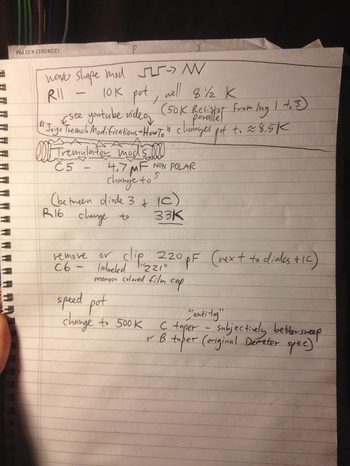
Modifying the Joyo Tremolo to Demeter Tremulator specs

The Joyo Tremolo is a "pretty good" tremolo out of the box for under $30, pleasant and traditional tremolo sound.  It is also very close to the Demeter Tremulator ($200) and can pretty easily made to sound almost exactly the same.

First a review of the build quality.  Everything is PCB mounted except for the footswitch, which is connected on a 6-conductor ribbon cable which is extremely fragile and easy to damage when working the parts around.  Be very careful with these tiny wires, they snap almost by themselves.

The PCB is pretty weak, I had several pads lift when re-working parts, so be as gentle as you can when doing the re-work.  This is not a pedal to work on over and over, it will fall apart.  Like the Behringer and Alesis compressors in some of my recent posts, this is not a product that's been built to last or really even be repaired.

Luckily the enclosure is pretty solid, the jacks are standard quality, not the worst, and the footswitch is a pretty standard 3PDT as well.  It seems like if you can get the work done and get it back together, it might last a while.

I really like this after the mods, it sounds exactly like Radiohead stuff with the Tremulator.  In my mind this is what a pedal tremolo should ideally sound like--excellent.

This is the video where I got these ideas from:
http://youtu.be/aB5xV99VXKI He also has a square to triangle wave shape pot mod that I skipped.  I found one more improvement on his mods as well, he didn't change the rate pot to Demeter value.  Without this mod the rate pot has a very bad range.

MOD LIST:
C5 - Change to 4.7 uF **non-polar**
R16 - change to 33K
C6 - remove 220pF cap
Rate Pot - change to 500K B or C taper
Optoisolator Bias Trim Pot - adjust to deepest setting for full silence on maximum intensity.  Or back it off if you like that gentle sound.  I like the dramatic deeper one, sounds more like a Tremulator to me.

R16 is right between diode 3 and the IC next to it.

C6 is the maroon colored film cap code "221" next to the diodes.

C taper, Anti-Log, is a really good sweep on the rate knob.  B taper, linear, is Demeter spec and would probably be fine too, I used C.  So did Bajaman on his Trembulator.

I also had to drill around the power jack a bit to enlarge the hole since my rate pot was a bit thick and moved things around slightly when reassembled.

And then I put some fancy Demeter/Marshall style knobs, looks great sounds great!  I built a Tremulator from scratch, gave it to a friend, have missed it ever since, finally got one back in my collection for minimum investment...very satisfying.  And that's a cool mean dog graphic too.


Monday, March 2, 2015

diy SPEAKER SWITCHER / MONITOR CONTROLLER / LINE SELECTOR #1

I have been building some really good guitar FX lately but I'll blog those later maybe, especially the Klon research I've been doing is of interest.  But this fun and rewarding little project just came off the bench:

I was looking at the Hosa and Coleman line selectors but they were dissatisfying for a few reasons: price, build quality, form factor.  So I decided to knock together one of my own.

I got a single deck 4P3T rotary switch from eBay, from China, and it's pretty nice.  This is the most essential part of the project.  With the knob attached, it shifts very smoothly from one position to the next, no clunky or harsh feel.  So far the switch is feels reliable, and it's noiseless.

Basically the 4 poles of the switch are attached to a common pair of TRS jacks (yellow wire, Left Tip, blue wire Left Ring, orange wire Right Tip, grey wire Right Ring) and all the grounds are through the chassis.  Rotating the switch sends the balanced TRS pair to A, B, or C pairs of 1/4" TRS jacks.  You can use this 3-in to 1-out, or vice versa 3-outs from 1-in.  Right now I'm using it as an input selector.  DAC #1, DAC #2, and Mackie Mixer is #3 routed through the switch into my speaker setup.  It would work equally well for switching powered monitor pairs, or what have you.

The spacing in the enclousure was a bit tight with these open frame jacks, it would have probably been best to use all enclosed black type ones, or to measure and lay it out better before drilling.  I was just emptying out my parts bin and I used every stereo jack I had left.  With a modicum of organization and care, the wiring was fairly straightforward, and I did a lot of double checking as I went along.  This is not a difficult project.

You might want to use a plastic jack with no ground connection to isolate all the grounds.  But I am not getting any ground loop noise with my setup.  I figure I'll lift grounds inside the cable plugs if that ever comes up.  I was pleasantly surprised that I don't have to yet.  Quiet like the mouse.

A very useful little project that can be used for any number of common studio audio routing tasks.  Indispensable!  Neato!  Gee Whiz! And check out that cool vintage knob!


Saturday, February 21, 2015

DIY Keeley/BOSS DS-1 Ultra - All Seeing Eye mod!!! (Disambiguation)

I am a bit fanatical about the DS-1 pedal all the sudden.  They kept sending me made in Japan and made in Taiwan models with the rare diodes and op amps, that just sound great.  But finally they sent one with the shitty Mitsubishi op amp so it's time to do the Keeley mod.

This post is a disambiguation.  There are a lot of online "tutorials" bout how to do this Keeley mod yourself, but there's a lot of vague information about the clipping modes.

After an afternoon and evening of sleuthing and experimentation let me say this.  The "SEEING EYE" mod is simply replacing one of the stock dioes with a 3mm LED which is visible on the "TONE" word on the case, you drill it out with a 1/8" bit, and glue it in, and that's the SEEING EYE mod.

The ULTRA mod is the switched part.  With the switch in the "up" position this second diode is the stock diode, a 1N4148.  The "all seeing eye" glows brightly, and the sound is very similar to the standard BOSS DS-1 tone, but with Keeley's wonderful refinements.  When the switch is down, you put a second 3mm LED in series with the stock 4148 diode, for the "ULTRA" mode.  The Ultra mode is the down switch position and there is a diode in series with an LED for the second clipping diode only.  Along with the standard Seeing Eye mod.  The Seeing Eye glows less brightly in this down switch position.  The sound is much, much louder and the clipping is reduced, along with more bass frequencies being heard.

So to wrap it up, the first diode is permanently replaced with the Seeing Eye 3mm LED in the TONE text, and the second diode is replaced with a switching array that allows to you to go between the regular stock 4148 diode.  And a second position (down) which gives the Ultra mode of a 4148 diode in series with a 3mm LED which is not visible, it exists inside the case.

This is a wonderful modification for the shitty newer $20-30 DS-1 you can find used with the annoying sound.  The older Japan and Taiwan models with the Toshiba op amps should not be modified, they sound wonderful.  But with this Keeley setup, the newer DS-1 can sound each bit as good.  I especially like the Seeing Eye mode.  The Ultra mode is a bit off-base from how a DS-1 usually sounds, so I will have to find a use for it.  I am guessing it could prove useful as a bass guitar distortion.  The Seeing Eye mode is more of a general refinement of the stock DS-1 sound.

You can see my photos below for the pedal I modified, and the full list of Keeley mod instructions on a piece of notebook paper.  I also would recommend trying an older Japanese style DS-1.  I would also recommend the Wampler mods that are available online in instructional form.  I did the "JCM" and "18 Watt Marshall" mods and they are both pretty cool.  Now I have to pick a favorite!  Or not... I have 5 orange pedals sitting here now! 


Wednesday, February 11, 2015

Alesis 3630 modification. Is it good? Or the worst ever?

I picked up an Alesis 3630 for $24 on eBay.  I have heard so much about them I had to get to the bottom of it myself.  Also, Billy Corgan used it in his guitar rig on the huge sounding Mellon Collie and the Infinite Sadness, and Daft Punk as a master compressor on their huge sounding albums Homework and Discovery.  So there could be something to it...

The first "mod" is to get a 2 Amp power supply (wall wart) I hear that the original ones are quite wimpy.  This part was about $18.

The second mod is to replace the caps in the power section.  This is where I ran into trouble.  I used 2,200 uF caps in all four position, but then one of them exploded.  I replaced it and it exploded a second time!  This was terrifying and disheartening.  I have heard of this phenomenon but this is my first time encountering it.  I believe that 2,200 uF was far to big a value for C2 and C3, and they were probably drawing too much power.  So I replaced them with 220 uF caps (C2, C3) and C4 and C5 I returned back to their original 1000 uF value.  I was too nervous to try 2,200 uF in there again.

So I cleaned up the mess, replaced a ceramic cap that got shattered (!!) in the first explosion, and let it run for an hour and a half.  This was nerve wracking, I kept expecting more popping caps.  After about two hours I felt OK to put it back together and start passing audio.

Let me mention the first nightmare.  When I pulled the knobs off for the initial disassembly, about 5 or 6 pot shafts got ripped out along with the knobs... nasty.  I don't know if some hapless punter glued them on or what.  So ordering replacement pots, and doing that part of the job, added a lot of extra time and work to this apparently ridiculous project.

The audio quad op amps that came stock were a respectable TL084CN (earlier revisions had much worse).  But I had to see what all the upgrade fuss was about so I installed sockets and a pair of Burr Brown OPA4227PA.  The two of them cost me about $5 on eBay.  So now my total investment in this 3630, including pots, is around $50.  Not bad.

I also replaced C16 and I think C33? (the other side of the board) with Panasonic electrolytic caps, since they are in the audio path.

Removing those caps gave me a little room for the nasty part, which was ripping apart the quad op amps with angled cutters.  Once you get one half of the op amp's legs snipped, you can just wiggle it back and forth a bit and then the other half of the legs will break eventually.  After this, pull the legs out with a soldering iron and some tweezers or grabber of some sort.  Then you can clean up the holes with desoldering braid (and a very hot soldering iron).  Once the holes are nice and open, you can put in a socket.  Then you can put in your new C16/C33.  After all this brute nastiness, now it's time to gently slide in the Burr Brown op amps... ahh....

Another word of caution.  I think the ribbon cable leading to the LED meters could be kind of delicate so be careful.  My left side gain reduction meter doesn't work any more.  I don't know why, but maybe I was rough on the ribbon.

The 1/4" jacks also needed a heavy dose of contact cleaner, and I refreshed the solder points for good measure.  I was getting some audio glitches from here but not after the cleaning.

I don't know which was more disgusting to work on, the Alesis 3630, or the Behringer MDX2100 Composer.  Both pretty revolting.  But in the end, they are both nice compressors to have working in the rack.

How does it sound?  Dirty-six-dirty is about right.  You get this kind of cassette tape, gritty, slightly dark on top, sort of big on the bottom thing.  Think Daft Punk, or Mellon Collie guitars.  Things sound a bit bulbous and sort of cartoon-like, a little low-fi or fuzz around the edges.  Which can be a useful sound, to my ears.  The Composer is a lot crisper and cleaner.  Honestly it wasn't that bad pre-mod either.  By the way--If you own an earlier '90s pre-Rev D. model, you might have to add a couple caps in the detector circuit, you can google this mod.  Mine already had them.  You can also snip some jumpers to take the gate out of the circuit and clean up the sound, but I didn't do this, I guess I wanted it 'kind of stock'.  And if you've got an early one with a comparator IC as one of the quads, that should be replaced with an op amp as well.

This sounds nothing like a DBX.  The compressor's action is not so defined or obvious, or quick I guess.  The attack and release, ratio controls are also not as responsive as I'm used to hearing in other compressors.  You can really smash the gain reduction meters, it seems a lot of people use 3630 like this.

It's too early to tell how much I'll use this, but it has a flattering sound that can work great for fattening up a thin sounding fuzz bass, for example.  I'm sure it would work great in a live-instrument rack, too.

Worst compressor of all time?  I doubt it.  Not bad.  I can't tell you how good it feels to be done with this one though.  I do plan to use it and it's been sounding cool so far!  The power supply lesson learned the hard way was probably worth the project alone.