Friday, December 30, 2016

Apex 205 Ribbon Mic Mods and Re-Ribboning

INITIAL MODS

The first thing to do is ditch the yoke mount, which is not fit for any job, and get a decent shockmount from eBay China for about $10.  Make sure to get the right diameter for the mic body, about 48-55 mm mount worked for me.

Next you can take the mic apart and remove some of the fine mesh screen with pliers, and remove the resonator plate that's on top of the ribbon motor.  This is well documented on other blogs and I didn't take any pictures.

My important distinction from other modders is I left these with a 2-layer headbasket.  I wanted just that little bit extra of wind protection.  When you get the 1.8 micron ribbon in there, it will bend and move with the slightest breath of air or move of the mic.  I would not be comfortable using this mic with a single layer headbasket.  That was my judgement anyway.  Look at any AEA, Coles, etc and you will see that a little bit of headbasket is just fine.

Removing all these acoustic layers cleans up the sound of the mic quite a bit.  The heavy mid hump clears up a bit and the top gets more open, you can hear this well at this blog along with his instruction guide for the mod:

http://www.hometracked.com/2007/08/17/ribbon-mic-mod-part-1-apex-205/
http://www.hometracked.com/2007/08/18/ribbon-mic-mod-part-2-before-and-after/

At this point the mic has shaped up quite a bit from how it was shipped from the factory.  But there's more to be done to make it compete with more expensive mics.

ADVANCED MODS - REPLACING THE RIBBON

That was the easy part!  These mics come with very thick 6 micron ribbons, despite what any of the Apex spec sheets might claim.  I held up my Apex 6 micron ribbon next to some 1.8u foil and with a slight blow, the difference was obvious.  Michael Joly made a little video with a pencil to show this to the internet, so I had to try it myself.

I ordered my 1.8u foil and my Tube Wringer corrugator from a seller called Geistnote.  He sells on ebay but also has a store you can find on google.

Watching his demonstration video really helped me a lot, I would recommend it.

I got a ruler and a cutting mat from Wal Mart.  You also need a razor blade, some tweezers, a screwdriver, and some needle nose pliers, as well as a soldering iron, some scissors, etc.

My first attemps with this DIY jig were a complete failure:


So I took a few days off and got the Tube Wringer from Geistnote, along with some more foil.  The main thing that's way better about it are the gears are more perfectly aligned, and much wider surface area.

My DIY Jig ribbons were coming out all crooked, which is bad.  The corrugations need to go on straight and symmetrical, otherwise the ribbon will hang at weird angles in the magnet gap.  This is possible also to go wrong with the Tube Wringer but it has been quite a bit more consistent in my use, with proper and ideal technique.

Also I learned that a piece of plain white paper is absolutely necessary for the way I work.  It helps to stabilize the aluminum as it feeds through the gears, and protects it from rips and tears.  Geistnote suggests even doubling up the paper.  Really I would suggest to take a look at his short video.

You just fold the paper in half, cut a piece of ribbon, and carefully place it in the bottom of the "V."  Now you are ready to corrugate.  Don't squeeze too hard you can rip the paper and the aluminum.  Chances are if it's your first try a few of your attemps are going to come out wrong.  Don't settle for any that have obvious flaws, it's better to get it just right.

By the third or fourth time with the folded paper, and the Tube Wringer, I was getting some nice ribbons.  I'm sure you could improve at this skill with more practice.

I would recommend to cut the aluminum about 1mm or so smaller than your actual magnet gap.  You want probably less than 1mm of a gap on each side.

I used a ruler, the cutting mat, and a simple razor blade to make the cuts.  That was the easy part of the ribbon job.  The corrugating seemed to be the hardest part with the most room for error.

After you've got a nicely corrugated length of ribbon, give it a gentle stretch a few times, just like they used to do at RCA and BBC.  This will keep it from sagging over time, like so many Chinese stock ribbons.  Don't pull so hard you take out the corrugations, just a gentle exercise.

I found it absolutely necessary to completely remove the ribbon motor from the microphone to be able to work with the ribbon.

DO NOT attempt to desolder the red wires on the top of the motor, or you will end up with this awful situation:


There's a lot of heavy silver bearing solder and those fat wires are really on there.  You're going to end up melting the plastic piece.  I was able to recreate the plastic piece with some plexiglas I had in stock so lucky me.  But it would be better to avoid my mistake, here's afterwards:


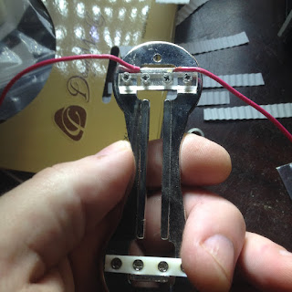
Now desolder the red and black wires from the PCB with the transformer on it.  This is the right way to get the ribbon motor free.  You should end up with something like this.  Now you'll be able to maneuver that gossamer strand of aluminum into the gap where it belongs.


You have a nice opportunity to clean up any debris that might be stuck to the motor here.  I used some tape to get off the tiny things that were on it.  And some tweezers for a bigger chunk of something.  You definitely want the cleanest possible gap between the magnets.

Hold your breath, breathe away from the aluminum.  I had to take some breathing breaks actually.  This stuff is LIVE when it comes to air movement.

Now carefully grab your ribbon.  Just lay it in there, see if it fits, see if it's straight.  If it looks good go ahead and drop the clamp on one end.  Give a little tension on the other and and drop the other clamp.  Use tweezers, toothpick, etc to get it to where it's just barely hanging straight with no sag.  Tighten one end.  Check tension, tighten the other end.  This is the fiddly part, this is the expert part.  It's not a particularly easy, or fun job, but it feels great if you can pull it off.

Be wary of any metal tools or debris jumping right onto the magnet and ripping your ribbon into trash.  Wooden toothpick is a decent tool for working close to the magnets.  My tweezers seemed OK when kept on the far ends of the motor.  You could use some plastic clips maybe.  Just be patient and careful with those tiny nuts when tightening them down.  Don't drop them on the ribbon.  I ruined at least one good ribbon with mistakes like these.

If it looks great, trim off any excess.  Here's my two motors.


At this point  you are ready for reassembly and testing.

You can twist the red and black wires on the bottom, left side red/black, right side red/black.  But solder red with red and black with black to the transformer.  Michael Joly says this can reduce hum pickup but I heard absolutely no difference in the noise floor in my room.  Hmm.  Michael also suggests to keep the red wires on the same plane as the ribbon and as straight as possible.  Maybe you could tape them in place or something.  I found the wires not to twist very well in my mic, they are different gauges.  But I did it anyway, even though it looks crappy.

One of my motors had a more significant gap on one side, almost a full millimeter between the ribbon and magnet.  The other one was a little closer fit.  I was unsure if it would make a big difference, so I just went with it to see what would happen.  When I listened to the mics back to back on voice and guitar I could tell that both mics sounded almost identical, so everything was fine!  Got them both right on the first proper try, no retensioning or re-ribboning needed.  I would not be able to tell these apart in a blind A/B test.  Also the sensitivity was almost identical between both mics.  So do a good clean job, reasonably precise, but don't get obsessed over tiny geometries.  These are crude, yet precise, machines of music.

On reassembly, one of my mics had a flipped polarity.  So I exchanged the red and blue (pin 2 and 3) wires on the XLR side of the PCB to get a positive polarity on that mic.  The test I used was to say "PAHHHH" really loud and quickly and zoom in on the waveform in my DAW to see a rising wave on the first P transient.  The out of polarity mic had a negative/downward wave on the transient.  You absolutely must use a pop screen with these mics anywhere near a vocal.  Possibly even on a loud cabinet or other gusty instruments.


TRANSFORMER REPLACEMENT

The final thing I'll get around to is a simple transformer replacement.  I'm going to go with the Lundahl 2912 amorphous strip core transformers because I really love what I heard from Dr.Bill's piano vs the Coles on Gearslutz.  https://www.gearslutz.com/board/gear-shoot-outs-sound-file-comparisons-audio-tests/150891-ribbon-madness-some-comparisons.html

My plan for these 205s is they will be my "high fidelity" ribbons with very flat response and clear sound, so the Lundahl 2912 seems like the right choice.  I can't wait to find someone with an acoustic piano.  I wish I knew someone personally with AEA R84s for a shootout, I think these are in that general direction.

My MXL R40 and R80 will be my character ribbon mics, for drum room and amps and whatnot, along with possibly a Cascade Fathead BE down the line.  Maybe someday I'll get a Royer.

In the mean time these 205s really tickle my fancy.  There is something about the way they capture the top end that is just beautiful to me.  The re-ribbon is a night and day difference from the stock 6u ribbon sound, much more clear and open, better detail capture.  Stock transformers seem OK but I want to see what those Lundahl's can do.

Just a little top end shelf on acoustic guitar and these are bright as anything.

Have not tried them on drums yet but that will be a fun test.  I am waiting for my second shockmount.

On vocals I would suggest about a foot of distance or so, too close gets too boomy with this mic.  Do not forget that pop screen, not even for a minute.  You learn to respect the 1.8u aluminum after working with it.  Avoid phantom power.  This is all common ribbon knowledge, but should be mentioned.

I can already tell these are some mics that I'm going to be passionate about, I expect them to be favored for lots of situations.  I highly recommend taking on this project if you think you have the patience and detail commitment for the somewhat steep learning curve.  It took me 5 years to work up the courage but I'm glad I finally did it.  Also check out www.frontendaudio.com as a good source for these mics.  Get on their email list for occasional 15% off coupon codes!  No affiliation they have just been really good to me.  The Apex 205 would be recommended over the 210 type because the smaller body and head have less acoustic effects and ringing (thanks to Michael Joly for the observation).  You end up with something a little bit like the ShinyBox product.  That would be a fun shootout, too.  I do think these mics sound $400 good, or so.  Very impressive DIY project.  From el cheapo to elegant chappo.  Highly recommended!!


Wednesday, December 7, 2016

MXL 991 and CAD GXL 1200 Small Diaphragm Condenser Microphone Modifications

INTRODUCTION

I get really excited about working on microphones, the chinese SDC was an obvious choice of another avenue to go down.  I started with some MXL 991, the classic culprit in this sense, and then added a pair of CAD GXL 1200 to go a little off the beaten path.  I learned a lot, had a lot of fun, and ended up with four fairly decent mics to add to my collection.

The first thing I would like to note is that NOT ALL OF THESE MICROPHONES ARE IDENTICAL, which goes against the prevailing vague "wisdom" blowing around the nets.  Yes, several of them are, but many have small differences.  If you get really unlucky, you might end up with an SMD circuit board, which is much harder to work on.  This happened with my MXL V250 mics from Guitar Center.  I was hoping for the V57 "schoeps" boards with through hole components.  I will have to move ahead with my own circuits for those, or swap in the boards from the CAD GXL 2200 mics that came packaged with the GXL 1200.  That "Studio Pack" is a really cheap way to get an SDC and an LDC for next to nothing.  Comes with a shockmount, too, and a pop screen.

The V250 is just another version of the MXL 990.  I used www.recordinghacks.com as a resource to find out what's inside a lot of these mics, and to choose from the many options out there for modifying.  The Nady CM-90 looks very similar to these CAD GXL 1200 and is available brand new for only $35 at the time of this writing.

The way I proved that these mics are NOT IDENTICAL is to set up the final mod versions of the MXL 991 and the GXL 1200 back to back and do a mic test.  The CAD mics have a bulkier low end presence to them and a neutral top, and the MXL mics have a little more midrange warm kind of hump and a slightly sweeter, leaner sound, with a lot of high end.  This is obvious in a back to back A/B test, even when swapping the capsules, the difference is mostly in the mic body circuits.  The MXL mics capture more of a sense of space and distance, the CAD mics sit a little more flatly, a slightly less spacious capture... very slight but worth mentioning.

Later, I checked out the manufacturers published frequency repsonse graphs.  Sure enough, the CAD GXL 1200 is very flat in the high frequencies, with very small boosts.  The MXL 991 has a lot more HF boost, as well as a high mid boost.  The popular MXL 603 has yet another response curve.

MIC MODS - ELECTRICAL

The first thing to do with these mics is the electronics mod, the "Gus" mod named from the Group DIY thread.  You take the ceramic cap from the capsule to the FET on the back of the PCB and replace it with a 1000 pF cap of your choice.  Polystyrene is usually recommended, but I like Paper in Oil and happened to have a few, so I went with those.

The next step is to replace "C3" and "C4" with the biggest value film cap you can physically fit inside the mic bodies.  To further prove the point that these Chinese mics differ in some ways, the MXL mics had the expected 220n caps in these spots, while the CAD mics had a less typical 470n value in the same spots.  The biggest caps I could fit in these mics out of what I had in stock were some 680n Panasonic ECQ-V maroon colored film caps.  The science is that the larger capacitance value will extend LF response, and the film type has less audible coloration artifacts than the ceramic type.

The CAD body is heavier, and tighter on the inside when sliding the new caps in.  The MXL body is very thin and lightweight, with a little more room inside for bulky parts.  They seem to have the same external dimensions, and the capsules are interchangeable between the two.

I used some electrical tape to insulate the PCB from my Russian paper in oil caps, and to hold these large parts in place.

After these mods, you can expect a more clear sound with a more extended bass, and less distortion coloration.  A bigger, clearer sound.  There are some nice videos for these mods on YouTube if you search for the MXL 603 (which is the very similar sister mic to the 991).  This is a really easy and cheap way to improve the stock mics.

You are going to want to mod the capsules next, if you want the full "Mod Guy" suite...

ACOUSTIC CAPSULE MODS

The most important thing to note about working on the capsules is they are very delicate, and very sensitive to any sort of abuse or contamination.  I ruined one of my diaphragms in the learn the hard way approach.  Luckily, my V250s came in handy with some spare capsules that are identical to these SDC mics.  The V250s are going to be rebuilt with CK12 or M7/K47 capsules anyway.

The best method I found was to use a clean plastic bag to hold the delicate capsule parts while I was working on the head shells.  Also I handled the parts with some hemostats instead of my greasy fingers.  Make sure your work space is very clean, and wash your hands often.

To get the capsule apart, you can stick some hemostats into the two holes inside the retaining ring on the back of the capsule and turn counter clockwise to loosen it all the way out.  Some other folks used tweezers and other types of tools.

If you use pliers to unscrew the hex shaped screw that goes into the backplate, that whole assembly will come apart as well.  This is not really necessary to do, you could just leave the whole backplate assembly alone.  For some reason, I kept wanting to take them completely apart, maybe out of curiousity.

The two clear plastic rings that are lighter than feathers go between the diaphragm and the backplate as a spacer.  Make sure no filth gets on these.

The two small copper colored rings go between the backplate and the clear plastic acoustic network chamber as a spacer.  I have heard that Mark Fauxman at Samar Audio was modifying the acoustics of this chamber for different sounds for a while.  That goes beyond the scope of my interest in this project.  You want to make sure the holes all line up in a very specific way with the backplate.  I tried to get a picture of this.  Just put it back together the same way that it was from the factory.

Once you've got your capsule safely disassembled and cleanly tucked out of harms way, it's time to modify the capsule housing.

On the MXL mics, you can rip out the silver colored retaining ring that holds the screen in, and get the screen free.  It's just glued on.

On the CAD mics (Nady, etc,) with the "Grilled" headbasket you can remove the screen just by pulling it out.

On the MXL mics, you can grind down the edge of the capsule several millimeters, re-use the same screen, but this time place it INSIDE the head shell above the diaphragm/membrane.

On the CAD mics, the screen must be discarded, and a new one fabricated from screening material.  It needs to be a little bit larger than the old screen.  I used the inner mesh from an old Apex 460 headbasket I luckily had lying around.  Once again, this new screen goes inside the capsule, right between the headshell and the mylar diaphragm.  The ring around the edge of the diaphragm gives enough space away from the grill screen.

The CAD headbasket has a groove around the top of it.  You might think you could pry or hammer this apart somehow, but it's an optical illusion.  I tried.  The whole shell is a solid piece of metal, the groove is just carved in.  You have to grind off the entire bulk of the thing, including the "grille" pieces.  Maybe if you want you could saw it off and then work from there.

For the grinding, I used a simple inexpensive hand tool, the orbital sander, with 60 grit sandpaper.  I set the sander on its side and held the head shells up to it with pliers.  This is where most of my ugly scratches came from.  There are other ways to do this with less scratching, if you look around google for what other people have done.

Once your capsule is sufficiently low profile, then you can shape the remaining edges with large and small hand files to get a more rounded shape, more like a KM184 or something.

On the MXL 991, the edge is wider, so I filed in a soft "V" shape going to the center of the diaphragms.

The CAD mics have a thinner edge so I just rounded them off.

Finish with 120, 220, 320 sandpaper and polish with 0000 steel wool.  This should leave a fairly smooth surface.  I didn't care to polish the entire shell so my mics have some scratches and dings on them, as well as the round carved parts not matching the color of the head shell finish.

Clean off your dust with soap and water and allow the head shells to completely dry.  You can speed up the drying with a heat gun.  Now carefully re-assemble the capsules.

This was the most fun part of the whole mod process.  It went surprisingly quickly, and was quite satisfying to do.

If you have been successful, your capsules will sound more spacious and open, less closed in sounding, than the stock capsules.  Off axis response is better and there are less weird resonances.  This is sort of a dramatic difference if you can do an A/B test with your recorder.  The CAD "grilled" mics were particularly bad offenders, presenting a very muddled stock sound response.  It might seem scary, and there are opportunities to screw up, but this is the most rewarding part of all the modifications.  The electronics mods are necessary but less glamorous and exciting than physically reshaping the acoustic space of the mic element.  It's fun work!
TESTING AND ASSEMBLY

I noticed that none of these capsules are very closely matched.  I tried my best to get the closest ones into the same pairs of mics.  I also found a few with weird 7-8 KHz dips in them on a pink noise test, and tried to discard those.  It's possible those were the ones that were mishandled, contaminated, or damaged during my initial cavalier excitement.  My MXL pair is fairly well matched, albeit not perfectly so.  One of my CAD mics is noticeably darker in the treble and has a bigger bass, so these don't make the best stereo pair.

After quite a long time of assembly, matching, testing and calibration I ended up with four mics that vary slightly in frequency response, sensitivity, but the CAD and MXL have distinctive personalities of their own.  Even if the pairs aren't perfectly "matched."  Basically the MXLs are much brighter, and the CAD bodies have some sort of circuitry that gives a flatter treble response.  I have not analyzed the electrical circuits between these mics.  There is a possibility of some de-emphasis from a pair of capacitors in the "Schoeps" circuit.  Jim Williams on gearslutz noted that the MXL 990 has these caps in place, and the 991 does not.  One theory is that maybe the CAD GXL 1200 has these parts in the circuit.  There is a pair of 150K bias resistors across the output transistor pair that comes after the C3 and C4 coupling caps.  The HF attenuating caps I believe are supposed to go in parallel with the 150K resistors.  JJ Audio suggests a value of 470 pF to 2200 pF.  The 990 circuit uses 1000 pF.  The real-deal Schoeps circuit also uses these hi cut caps.  You could tame the treble peak on the 991 by soldering some of these caps to the back of the circuit board, 63 Volt or higher rating recommended.

I have to give Jim Williams personally a lot of credit for getting me excited about these mics, he's posted a lot of great info about them over the years, as well as favorable reviews.  His electronics mods are much more involved than the "Gus" mod.  I think the microphoneparts.com PCB kit incorporates a lot of those tweaks.

DAY 2: VENT MODS

Some folks, JJ Audio, Oktavamod, like to enlarge the side vents on the body.  After reading, and listening, I decided it was a good idea.  The main thing you hope to accomplish is flatten out that big 7-10KHz or so presence boost.

I used the tools I had on hand, but a Dremel type rotary tool probably would have been better.  First, pull out the screens with some sort of hemostats, picks, or tweezers.  Be careful not to damage the screens, you will need to put them back in later.

Next, destroy the vents.  I started with a small drill bit to make a hole in the middle of the 4 vent pieces.  Then I went through it with a larger drill bit.  At this point I started ripping off the pieces with needle nose pliers.

The thicker, heavier CAD body is a little harder to work on.  The flimsy little MXL bodies came apart very easily.

Be very careful not to get too "enthusiastic" at this stage because you can easily damage your threads or misshape the threaded edge of the body.  I did this a little bit when I was rushing through my last one, but I was able to salvage it, thankfully.

Once you've got big gaping holes in the side of your mic bodies, file down any sharp edges or leftover bits with small files.  If you want to be careful and artful you can probably clean up the appearance a bit and make things look nice.  Or you can get to the point and just make sure there's nothing sharp that will catch your fingers, and have a couple rough and ready looking cuts on your mics.  They don't look great, but they also don't look too bad.  My mics are all scratched up anyway.

Wash and dry the bodies from all this grinding dust residue.

The most complicated part is putting the screens back in.  Once your screen is roughly in place, put a dab of glue on all four sides where it touches the body, I used super glue.  Then use a small clamping hemostat or some other tiny clamp to hold the edges down flush while it dries.

Come back after some coffee and snacks, or another day, and continue.  I was in a rush so I sped up the curing and drying of the super glue with my heat gun.  I didn't want any off gassing from the glue to get on my capsules.  The heat gun will speed up the drying process, watch your eyes though, the gasses will start to come off pretty quickly when it gets hot.

At this point you can reassemble your mics and plug them in.  There is very little chance of error in this vent mod step, other than the threads, so the mics should work immediately.

When I did an A/B listening test of the vent mod mic, and the stock vent mic, I could clearly hear that artificial 10-20 KHz "zing" disappear from my acoustic guitar.   Nice!  After living with the mics for 24 hours I was not happy with that too-hyped top end boost.  I also found myself filtering out these frequencies on drum overheads, the cymbals were just getting too bright up there in my untreated drum room.  After the vent mods, things should smooth right out, and the mics will give a more natural sound.

This part of the mod is slightly challenging, but I would highly recommend doing it.  Props to Michael Joly at OktavaMod I guess for apparently popularizing or discovering this part of the mod.  If you're in for some good lulz head over to gearslutz and check out all the Mic Mod Guys arguing with each other about who did what first.

WHOOPS, MY BAD

Once, I assembled the capsules with a little water and/or alcohol in them and was greeted with harsh noise, no sound at all, and all sorts of calamities.  But do not fear, this is part of the game.  I just took them apart, cleaned them again, and put them back together making sure they were completely dry, and the mics worked as fine as ever.  Crisis averted.  This is just the way it goes with DIY building, you learn to troubleshoot.  Compressed air from a blow can is a good way to dry the capsule backplate.  You can wash it with soap and water to make sure it's completely clean.

After I learned from my first too eager mistake, I made sure to dry all the head shells with a heat gun on a low setting so no moisture entered my capsules when reassembled.  You could do the same thing with a blow drier.  The alcohol came from a moment when I was cleaning one of the mics with a small brush.  I would not recommend getting alcohol or any liquid on the assembled capsule, it can go right into the acoustic chamber.

The gold plated diaphragms you don't want to touch at all.  Your best bet there is to keep them as super clean as you possibly can the whole time you are working.  That is why I recommend a clean plastic bag as a containment.  Never touch them with your fingers or any hard objects.  Never set them on a dirty table or desk.  If your capsule is damaged, you'll probably hear it as a wonky sound of some sort during your recording tests.  My damaged capsule sounded honky in the mids with weak bass and high frequencies.

RESULTS AND OBSERVATIONS

In their stock forms, these mics would not find a place in my personal mid-end studio.  They're just not good enough if you've been around the block a few times, or if you are a full-fledged Gear Head.  The stock CADs were particularly bad.  The stock MXL fared a little better.

On the other hand, for about $30 each, I would absolutely recommend them to someone just starting out.  You could learn a lot about recording with these, without getting too caught up in the "fidelity."  Which is something I get more and more caught up in these days.  The ISK Little Gem is another nice inexpensive condenser with multiple patterns.

Would I recommend buying some of these and sending them to Michael Joly for his expensive service of the same thing I just did here?  Probably not.  Well...maybe.  At the $350 per mic price point, you're going to be wanting to look at some very sweet options like the vintage AKG C451E or C451EB, the Shure KSM141, or a pair of  KSM137, the Peluso CEMC6, or ones I haven't tried such as the Advanced Audio CM 1084, a pair of Lauten Audio LA-120 and so on.

Some of these mics are comparable to the modified CAD and MXL, and some are even better.  On top of that, a lot of them have added features that these mics will never have, like pads, additional patterns, filters, and so on.  And across the board a better build quality.  At the moment, the Advanced Audio really catches my eye because of its multiple patterns and the fact that it's transformer coupled, which is part of what I really liked about the AKG C451, and which is what a lot of people partially like about the KM84.

In some ways these mics are completely transformed from how they started.  I would say they sound as good as a $300 microphone after the complete mod suite, to state it roughly.  They will never sound as good as the $600 or $1,000 microphones I have used, due to the limitations of the capsule mainly, and the amplifier as well.  However that's a factor of 10 increase in perceived value, and a lot of mid-priced mics are very useful indeed.  You could go nuts with the Microphone Parts .Com circuit boards, but once again, I would throw that money at a better mic to begin with.  The "Gus" electronics mod seems sufficient.  The main idea here is to see how much sweat equity you can put into this bargain basement mic mod platform, to turn the sows ear into a silk purse, not to throw a bunch of money at it.  They look pretty crappy compared to a well-maintained freshly manufactured microphone.  I guess the rat rod look can be appealing.  You could always spray paint them, or have them powdercoated.

IN USE - HOW DO THEY SOUND

I went back and listened to some sound files of my old KM184, C451E, and CEMC6.  I found the AKG and Neumann mics to have more weight and character to their sounds than these mods in most of my clips.  If you've done the full mod suite though your CADs or MXLs should give a pretty high fidelity capture.  I think they might sound similar, or even better, to the Peluso CEMC6, which is a slightly expensive stereo pair, so that's a pretty good outcome.  I sold the Peluso's because they had too much top end hype or zing to them, which seems to be a common theme with a lot of SDC mics, and which is something more under your control in a DIY situation.

In my recording tests, both sets of mics showed good results on acoustic guitar.  You would want to use the MXL to brighten up a dull sounding instrument, and the CAD on something that's already bright as to not overdo the top end.  Both are good.  The MXL would probably be more flattering to finger picking and soft playing, it adds some excitement and air to the sound.  The sparkle and harmonics of the MXL are very flattering to acoustic instruments.

In XY over the drum set, the CAD mics are superior.  The MXLs hype the cymbals too much and they take over the mix and sound splattery and out of control, even after all these mods.  The CAD mics keep them sitting nicely balanced with the rest of the drum set, even with hard cymbal strikes.  So I guess the CAD is the surprising winner here.  I was very happy with my overall drum sound.  I'd be happy to use these mics on a session, next to any of my more expensive stuff.  If you only have the MXL and want them to sound more flattering on drums and cymbals, you can add the HF cutting caps I mentioned earlier.

The closest things these remind me of in terms of price and performance are the Oktava MK 012, but I think these might be even better after the mods.  I never liked the stock Oktavas over a drum set.  It would be fun to do the Dorsey mod on a pair of Oktavas and compare them to these.  Apparently Mr. Joly rates the modded Chinese SDC and modded Oktavas both fairly well, so that's something I'd like to look into.  His website is a good resource for sound samples of fully modded mics vs. expensive mics.

EDIT: 2-26-2018

I find that the MXL 991 are basically not very good at anything.  The CAD GXL1200 on the other hand, I would recommend on modding.  They sound better in every application.  They are still "bright" microphones, with a big puffy top end, which you might want once in a while.

I think the MXL 991 I am going to gut and do one of those MicrophoneParts circuit replacement kits, and maybe try one of their capsules.


PICTURES - A THOUSAND WORDS


Monday, December 5, 2016

DIY Z VEX Super Duper 2-In-1 pedal and stripboard layout (schematic)


If you want to go straight to the stripboard layout, scroll to the bottom of this post.

I used Iviark's nice layout as a starting point, and did some research to reach what I believe is the "final" schematic or layout.

The main difference from the Super Hard On is the input caps need to be reduced to .01 uF as per Zachary Vex's post on The Gear Page.  If you use the stock 100n SHO input caps, the subsonic frequencies can cause the pedal to "drop out" or "shudder" at high gain settings.  The slightly smaller input cap value cures this problem, so use it.

Also, the second SHO in this box, the "red side," you need to drop the 100K bleeder resistor completely, just remove it from the layout, and add a 50K volume pot, the master volume control, which is the center knob in my build and Z Vex's also.  If you look at gut shot pics of the 2-in-1 you can see that this pot is a 50K, not a 100K.  This gives the "red" side a slightly warmer top end.  I think a cool mod for a SHO would be just to use a 50K bleeder resistor in place of the 100K if you think the sparkle is too much (which I sometimes do).

My stripboard layout posted here includes all these corrections.

I built two of these, one with mid grade black Nichicon output electrolytic caps, and one with the Nichicon Fine Gold output caps.  The Fine Gold caps give the pedal more clarity, so I chose to build that one up first, and that would be my recommended part.

I used the ceramic input caps because Zachary uses those in his pedals, I figure maybe it's a small part of the tone.  If you want a super transparent circuit, you can replace those with polypropylene, paper in oil, or etc caps for super transparency.  I built up a Landgraff Boost with caps like that, and it's probably the most transparent boost that I have heard.  By the way, the Landgraff is simply a rip off of the ZVex circuit, the only difference is the brand of FET employed, and the capacitor type choices.  Surprisingly, these small differences are audible in a side-by-side comparison, which I have done.

This would not be my recommended build for a first timer, due to the complexity of the offboard wiring.  I would get comfortable with single boost pedals before attempting a dual footwsitch circuit.

SOUND REVIEW

I am sort of a clean boost fanatic, I have almost a dozen of them lying around here.  This one very quickly has earned my attention.

The main thing that's great about the 2-in-1 is the versatility of tones available in this very compact box.  The single SHO, the "yellow" side, is a pretty bright and sparkly boost.  Good for clean tones, maybe, in my opinion.  The "red" side with the master volume has a slightly warmer tone, due to the output pot impedance, and due to the fact that you can dial in more clipping with the master volume at lower levels.  And of course you can ram the yellow into the red for even more coloration, or stacking of tones.  The "red" side seems to be the more special part of this pedal, for my purposes.

The really interesting part of this circuit as a distortion device is it's a completely flat frequency, broad band response.  You can dial it in to a medium gain at unity volume, play lightly, switch the pedal ond and off, and the true bypass tone sounds almost identical to the ZVEX tone.  Then you play harder and the clipping shows up.  It doesn't "hump" your tone like an overdrive pedal.  So you can use the controls available to add any combination of volume changes, and clipping changes, that you like, along with whatever your amp and your other pedals are doing.  It's just a fairly elegant part of the gain staging of the entire guitar rig.  It's transparent enough that it doesn't mess with your tones too much.  It seems like most tube amps like to be hit a little bit on the front end, more often than not.  Especially at low or medium volume, when the output section is not working as hard.

I have used other clean boosts that were way too sparkly on top (Boost N Buff), and some others that seems slightly too dark and mushy (Keely Katana), my favorites seem to lie somewhere in between.  This one gives you a little of both, plus more control over the grit.  Sort of like a Fulltone Fat Boost, but more clear and transparent.  A feature I am sure of the simplicity of the circuit design.

I would not use this as my main distortion or overdrive, it is not a substitute for those.  But I think every pedalboard deserves a boost, and this is a great one.  My simple test was to run my Agile les paul into my Blackstar Studio 20H amp head.  When I turned the boost on, the clean channel just sounded better.  By itself the amp was slightly dark and soft sounding, but the 2-In-1 just firmed it right up and gave a solid and authoritative tone, when used as a buffer or a moderate boost.  There's a lot of subtle, tweaky ground to cover with the three controls and both footswitches, which made me happy.  You're not just stuck with one sound.  It didn't seem to do much for the distortion channel, I will stick to my overdrive type pedals for that kind of boosting, where the mid-humping type of sound comes in handy.

My favorite boost to date seems to be the Xotic EP Booster, which has a spot on my large pedalboard.  And the DAM Red Rooster, which is more of a character germanium treble booster on the front end of things.  The Landgraff boosts I built are among my most favorite "one knob" boosters, along with an honorable mention of the MXR Micro Amp, which I used for some time.

The question to me seems to be, how does this compare to the Super Hard On?  I found the single, stock SHO to be slightly too sparkly on the top, which is why I favored the Landgraff versions.  That SHO/Boost 'N Buff presence bump can seem sort of tacked on, or artificial, when running a good tube amp.  But with the master volume "red" side on this pedal, this one seems even more versatile than the Landgraff, and better sounding than the single SHO.  I think this pedal is more useful than the seemingly "too simple" Super Hard On, and depending on your build, not even that much bigger, or perhaps the same size, so why not?

I will also recommend to use the top jacks if you can manage, it makes for cleaner cabling than the side jacks on this sideways pedal.  Happy soldering and good boosting to you. :-D


UPDATE: 5-21-20

That pedal was gifted to a friend.  Here is my second personal build.  Still like this thing.  In this build, I changed the MOSFETS to NTE 490 as per Landgraff.  Pinout is the same as the BS170, transistors are about twice as expensive (About a buck vs. about 50 cents).  But I find them fatter and warmer sounding in these types of circuits.

I also used the DAM footswitch wiring, which puts the LED current limiting resistor on the footswitch, rather than the PCB.  Any footswitch wiring standard will work, as long as you mind your ins and outs.  For simplicity, you can just stick to the modded IvIark layout below.

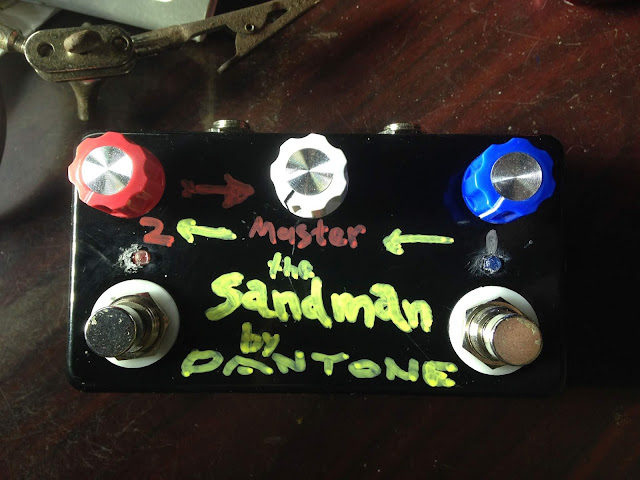
Here's my new build, The Sandman